Speed-recognition-based automatic fixture for robot

A voice recognition and robot technology, applied in chucks, manipulators, manufacturing tools, etc., can solve problems such as safety accidents and affecting the use of fixtures, and achieve the effects of protecting workpieces, facilitating processing and use, and convenient operation

Pending Publication Date: 2019-03-01
宁波帮手机器人有限公司
View PDF11 Cites 8 Cited by
  • Summary
  • Abstract
  • Description
  • Claims
  • Application Information

AI Technical Summary

Problems solved by technology

[0003] A Chinese patent (notification number: CN 208132993 U, announcement date: 2018.11.23) discloses an industrial robot fixture for processing. Although its structure can hold the workpiece, the workpiece needs to be manually placed on both sides during installation. Between the splints, carry out related clamping. If the machine and people do not cooperate well in this operation, it is easy to cause safety accidents and affect the use of the clamps.

Method used


Image

  • Speed-recognition-based automatic fixture for robot
  • Speed-recognition-based automatic fixture for robot
  • Speed-recognition-based automatic fixture for robot

Examples


Embodiment 1

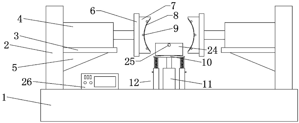
[0021] Please refer to the figure, in the embodiment of the present invention, a robot automatic fixture based on speech recognition includes a base 1, a side support 2, a cylinder seat 3, a clamping cylinder 4, a rib 5 and a splint 6; the base 1 Both ends are fixed with vertical side brackets 2, and the cylinder block 3 is horizontally fixed in the middle of the side bracket 2, and is fixedly welded by reinforcing ribs 5 to enhance the strength of the cylinder block 3, and the cylinder blocks 3 on both sides are on the same horizontal plane. The clamping cylinder 4 is horizontally installed on the cylinder base 3, and a vertical splint 6 is fixed on the end of the output shaft of the clamping cylinder 4 on both sides. Move so that the splints 6 on both sides apply pressure to the workpiece.

[0022] The same clamping blocks 7 are fixedly installed on the splints 6 on both sides, and the two clamping blocks 7 are arranged opposite to each other. The opposite side walls of the ...

Embodiment 2

[0026]A plurality of first pressure sensors 9 are installed on the clamping block 7, a second pressure sensor 23 is installed on the top of the placement plate 10, a speech recognition module 25 is installed on the baffle plate 24, and a controller is installed on the base 1 26. The clamping cylinder 4, the first pressure sensor 9, the lifting cylinder 11, the second pressure sensor 23, and the voice recognition module 25 are all connected to the controller 26, and the first pressure sensor 9, the second pressure sensor 23 , the voice recognition module 25 is connected to the input end of the controller 26, and the clamping cylinder 4 and the lifting cylinder 11 are connected to the output end of the controller 26, and the first pressure sensor 9, the second pressure sensor 23, and the voice recognition module 25 will monitor the The signal is transmitted to the controller 26, and the action of the clamping cylinder 4 and the lifting cylinder 11 is controlled according to the i...


PUM

PropertyMeasurementUnit
Thicknessaaaaaaaaaa

Abstract

The invention relates to the field of automatic equipment and particularly discloses a speed-recognition-based fixture for a robot. The fixture comprises a base, side supports, cylinder seats, clamping cylinders, reinforcing ribs and clamping plates. Identical clamping blocks are fixedly mounted on the clamping plates on the two sides. A vertical lifting cylinder is fixedly arranged in the centerpoint of the base. A horizontal carrying plate is fixed to the output end of the lifting cylinder. The two sides of the lower side of the carrying plate are both provided with vertical height adjusting mechanisms. The clamping cylinders, first pressure sensors, the lifting cylinder, second pressure sensors and speed recognition modules are all connected to a controller. The fixture is manually controlled to start. The fixture is started by manually pressing and providing speed input. Moreover, after the fixture is started, there is no need to manually and continuously hold a workpiece until the workpiece is clamped, so that occurrence of some safety accidents are avoided. Thus, the fixture is safer in workpiece clamping, high in automation degree, convenient to operate and capable of saving time and labor.

Description

technical field [0001] The invention relates to the field of automation equipment, in particular to an automatic clamp for a robot based on speech recognition. Background technique [0002] A robot is a machine device that performs work automatically. It can accept human command, run pre-programmed programs, and act according to principles formulated with artificial intelligence technology. Its mission is to assist or replace human work in jobs such as manufacturing, construction, or hazardous jobs. Today's robots have been applied in the field of metal processing, and clamping devices are often required in the process of metal processing. [0003] A Chinese patent (notification number: CN 208132993 U, announcement date: 2018.11.23) discloses an industrial robot fixture for processing. Although its structure can hold the workpiece, the workpiece needs to be manually placed on both sides during installation. Between the splints, perform related clamping. If the machine and...

Claims


Application Information

Patent Timeline
IPC IPC(8): B25J15/00B25J19/02
CPCB25J15/00B25J19/02
Inventor 刘刚孙平波
Owner 宁波帮手机器人有限公司
Why Eureka
Try Eureka