
Deburring device for scrap edge of cold-rolled steel strip

A cold-rolled steel strip and deburring technology, applied in metal processing equipment, maintenance and safety accessories, metal processing machinery parts, etc., can solve problems such as processing difficulties, iron filings polluting the working environment, difficult steel strip position adjustment, etc., to achieve High practical value, avoid polluting the workplace, and ensure the effect of correct processing

Active Publication Date: 2019-03-01
广西盛隆钢铁材料研究院有限公司
View PDF13 Cites 3 Cited by
  • Summary
  • Abstract
  • Description
  • Claims
  • Application Information

AI Technical Summary

Problems solved by technology

[0002] Steel strip is a commonly used material, which is mainly processed by cold rolling or hot rolling. However, during the processing of cold rolled steel strip, due to the uneven force on the outer material, a large number of burrs and waste edges will appear on the edge of the steel strip. Therefore, reasonable cutting is required to ensure the stability of the performance of the steel strip and meet the requirements for the stroke and matching accuracy of the steel strip during use. The existing deburring of the steel strip is mainly directly manual grinding with a flywheel or a fixed grinding tool. Grinding, it is difficult to adjust the position in time for steel strips of different widths and heights, resulting in processing difficulties, and the existing deburring mechanism also lacks iron filings collection equipment, resulting in iron filings polluting the working environment

Method used


Image

  • Deburring device for scrap edge of cold-rolled steel strip
  • Deburring device for scrap edge of cold-rolled steel strip
  • Deburring device for scrap edge of cold-rolled steel strip

Examples


Embodiment Construction

[0019] The following will clearly and completely describe the technical solutions in the embodiments of the present invention with reference to the accompanying drawings in the embodiments of the present invention. Obviously, the described embodiments are only some, not all, embodiments of the present invention. Based on the technical solutions in the present invention, all other embodiments obtained by persons of ordinary skill in the art without making creative efforts belong to the protection scope of the present invention.

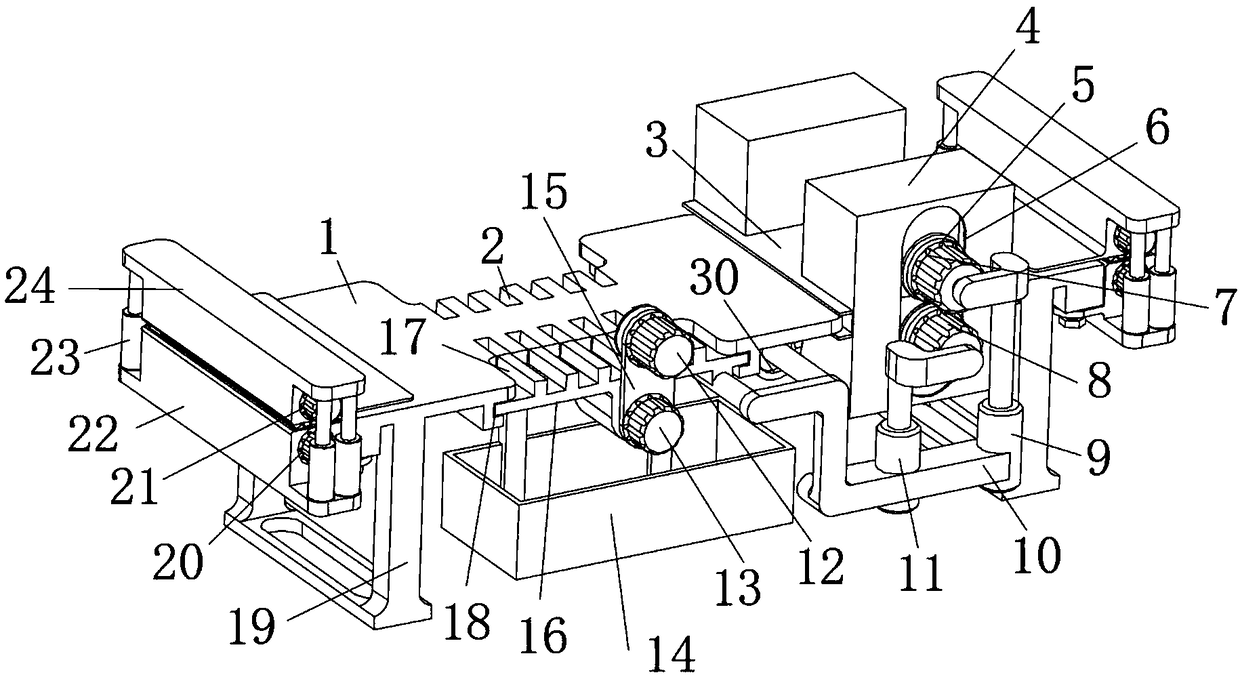
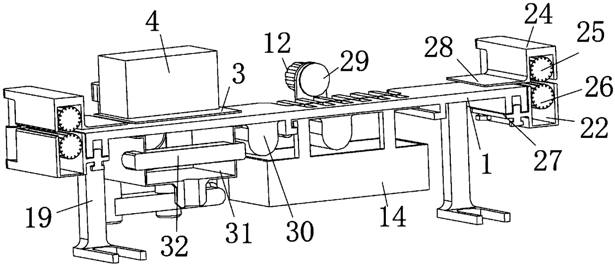
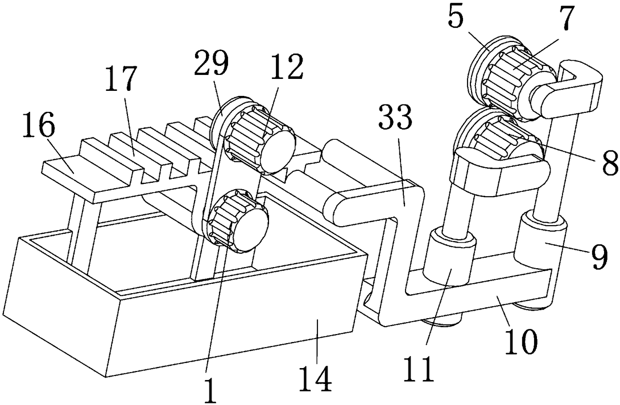
[0020] see Figure 1 to Figure 4 , the present invention provides a technical solution: a cold-rolled steel strip trimming and deburring device, including a workbench 1, and the lower part of the workbench 1 is supported by a support seat 19, and the left and right ends of the workbench 1 are fixed and installed by bolts There is a fixed plate 27, and a fixed seat 22 is integrally formed on the fixed plate 27, the first roller 26 is installed through a...


PUM


Abstract

The invention relates to the technical field of machining and discloses a deburring device for the scrap edge of a cold-rolled steel strip. The deburring device comprises a workbench, wherein supportseats are arranged below the workbench to support the workbench; fixed plates are fixedly mounted at the left and right ends of the workbench through bolts; fixed seats are formed integrally on the fixed plates; first rollers are mounted on the fixed seats through bearings; and first-roller drive motors used for driving the first rollers are fixedly mounted on the fixed seats through bolts. The deburring device designed by the invention can adjust the working positions of a cutting tool and grinding tools through position adjusting push rods according to the width of the steel strip as well asadjust the clamping positions of second rollers through movable-seat driving push rods according to the height of the steel strip, so as to ensure the correct machining of the steel strip. Also, thedeburring device can reasonably collect iron chips generated during the machining process of the steel strip, so as to avoid polluting a workplace. Therefore, the deburring device is of high practicalvalue.

Description

technical field [0001] The invention relates to the technical field of mechanical processing, in particular to an edge trimming and deburring device for a cold-rolled steel strip. Background technique [0002] Steel strip is a commonly used material, which is mainly processed by cold rolling or hot rolling. However, during the processing of cold rolled steel strip, due to the uneven force on the outer material, a large number of burrs and waste edges will appear on the edge of the steel strip. Therefore, reasonable cutting is required to ensure the stability of the performance of the steel strip and meet the requirements for the stroke and matching accuracy of the steel strip during use. The existing deburring of the steel strip is mainly directly manual grinding with a flywheel or a fixed grinding tool. Grinding, it is difficult to timely adjust the position of steel strips of different widths and heights, resulting in processing difficulties, and the existing deburring mec...

Claims


Application Information

Patent Timeline
Patent Type & Authority Applications(China)
IPC IPC(8): B23P23/04B23Q11/00
CPCB23P23/04B23Q11/0042
Inventor 不公告发明人
Owner 广西盛隆钢铁材料研究院有限公司
Learn More