Polishing machine

The technology of a polishing machine and a polishing device, which is applied in the field of polishing machines, can solve problems such as the inability of polishing machines to polish

Pending Publication Date: 2019-02-26
陈云飞
View PDF10 Cites 2 Cited by
  • Summary
  • Abstract
  • Description
  • Claims
  • Application Information

AI Technical Summary

Problems solved by technology

[0003] The purpose of the present invention is to provide a polishing machine to solve the technical problem that the polishing machine in the prior art cannot polish complex curved surfaces

Method used


Image

  • Polishing machine
  • Polishing machine
  • Polishing machine

Examples


specific Embodiment approach

[0056] Further, see Figure 5 to Figure 8 , as a specific embodiment of the jig device provided by the present invention, the water barrier assembly includes: a second sealing sleeve 26 , a second snap ring (not shown) and a second sealing ring 28 .

[0057] The second sealing sleeve 26 is sleeved on the outside of the connection between the base 25 and the first sealing sleeve 22 , and the inner wall of the second sealing sleeve 26 is formed with a second locking groove 261 and a second locking groove 261 ringed on the outside of the first sealing sleeve 22 . The flange 262 , the second locking groove 261 and the second flange 262 respectively extend along the circumferential direction of the second sealing sleeve 26 ;

[0058] The second snap ring is set in the second slot 261; and

[0059] The second sealing ring 28 is disposed between the first sealing sleeve 22 and the second sealing sleeve 26 , and the end surfaces of the second sealing ring 28 abut against the second f...

Embodiment approach

[0144] Further, see Figure 10 to Figure 12 As a specific embodiment of the angle adjustment lifting device 3 provided by the present invention, the connecting structure includes a roller 3311 arranged on the connecting rod 331 and a guide provided on the traction member 3323 for accommodating the roller 3311 and allowing the roller 3311 to slide The groove 33231 and the guide groove 33231 extend in directions perpendicular to the rotating shaft 3341 and the guide rail 3321 respectively.

[0145] In this embodiment, the connecting rod 331 is provided with a roller 3311, and the traction member 3323 is provided with a guide groove 33231. The guide groove 33231 is used to accommodate the roller 3311 and allow the roller 3311 to move in a direction perpendicular to the rotating shaft 3341 and the guide rail 3321 respectively. move. In this way, when the connecting rod 331 is moving, the connecting rod 331 will approach or move away from the guide rail 3321 in directions perpendi...


PUM


Abstract

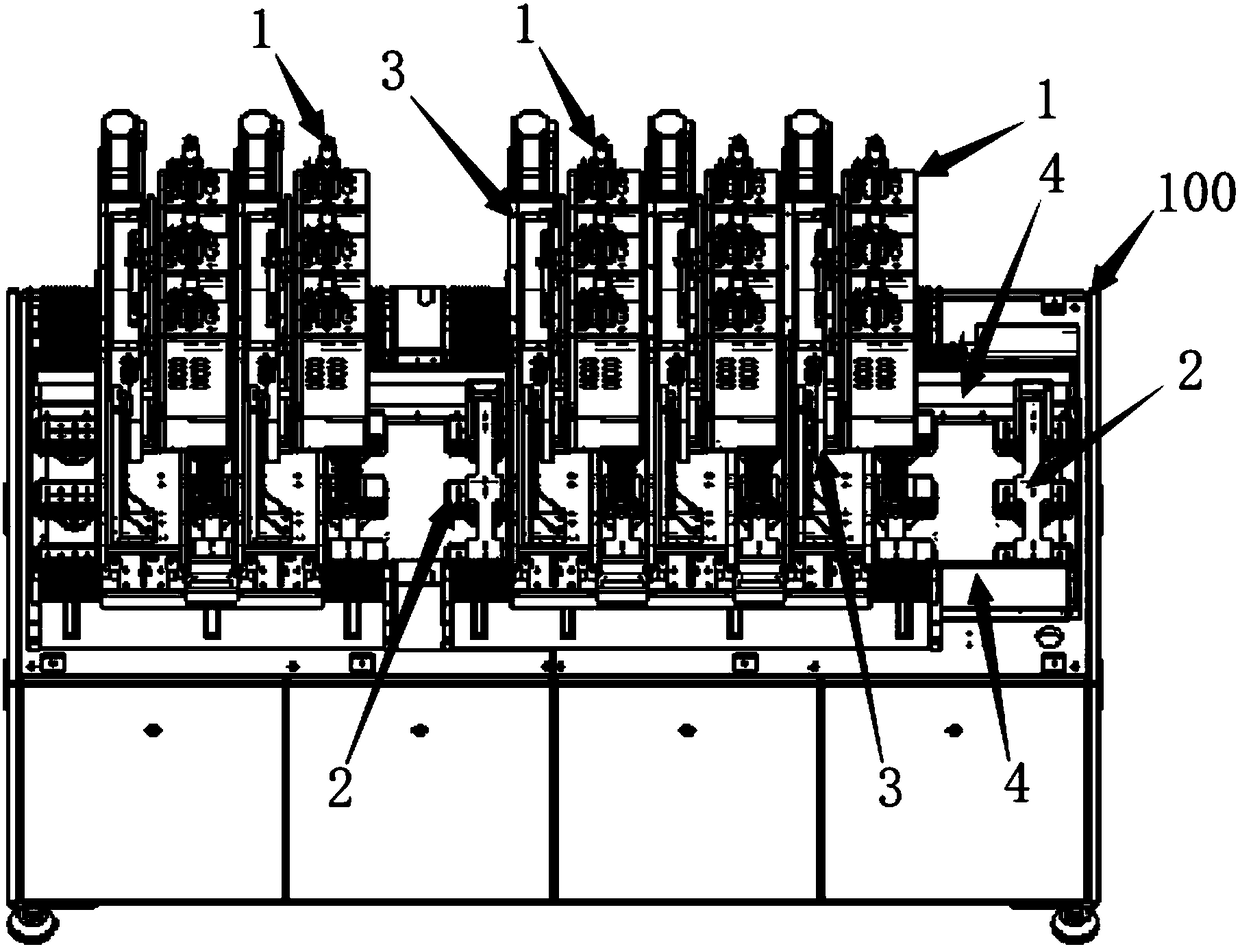
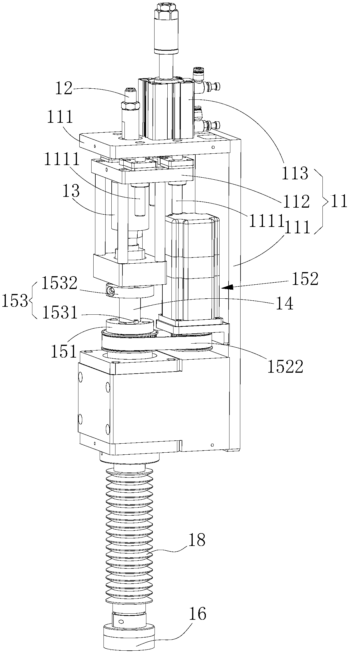
The invention relates to the technical field of polishing equipment and provides a polishing machine. The polishing machine comprises a rack, a jig device, a polishing device, an angle adjusting lifting device and a translation device. The jig device comprises a supporting frame which is used for supporting an object to be polished and can rotate by taking a first axis as a shaft, and the supporting frame is arranged on the rack; the polishing device comprises a polishing head which rotates by taking a second axis as the shaft and is used for polishing the object to be polished supported on the supporting frame; the angle adjusting lifting device is used for adjusting the included angle between the first axis and the second axis and driving the polishing device to move relative to the rackin the Z-axis direction; the translation device is used for driving the polishing device to move relative to the rack in the X-axis direction and the Y-axis direction. The translation device can drive the polishing device to move along the X-axis and the Y-axis directions and the angle adjusting lifting device drives the polishing device to move along the Z-axis direction, therefore the polishingdevice can achieve movement in three directions of X-axis, Y-axis and Z-axis under the driving of the translation device and the angle adjusting lifting device.

Description

technical field [0001] The invention belongs to the technical field of polishing equipment, and more specifically relates to a polishing machine. Background technique [0002] With the increasing weight of products, the polishing requirements for products are also increasing. Polishing can remove the rust on the surface of the product, and can also make the surface of the product smoother. In the 4G era, due to the electromagnetic shielding effect, the metal shell has to be made of plastics such as PPS ("PPS" refers to: polyphenylene sulfide), PBT ("PBT" refers to: polytetramethylene terephthalate) The material is isolated from multiple sections. In the future, we will enter the 5G era, and the communication signals will be more complex. NFC, WIFI, wireless charging, etc. will become standard configurations of mobile phones, and non-electromagnetic materials such as glass materials will usher in major opportunities. Curved display screens, curved wearable devices, etc. hav...

Claims


Application Information

Patent Timeline
Patent Type & Authority Applications(China)
IPC IPC(8): B24B29/02B24B41/06B24B41/02B24B41/00
CPCB24B29/02B24B41/00B24B41/02B24B41/06
Inventor 陈云飞
Owner 陈云飞
Why Eureka
Try Eureka