
Flexible display device

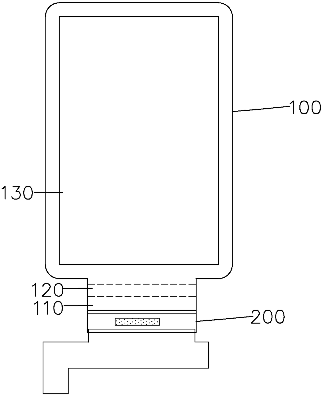
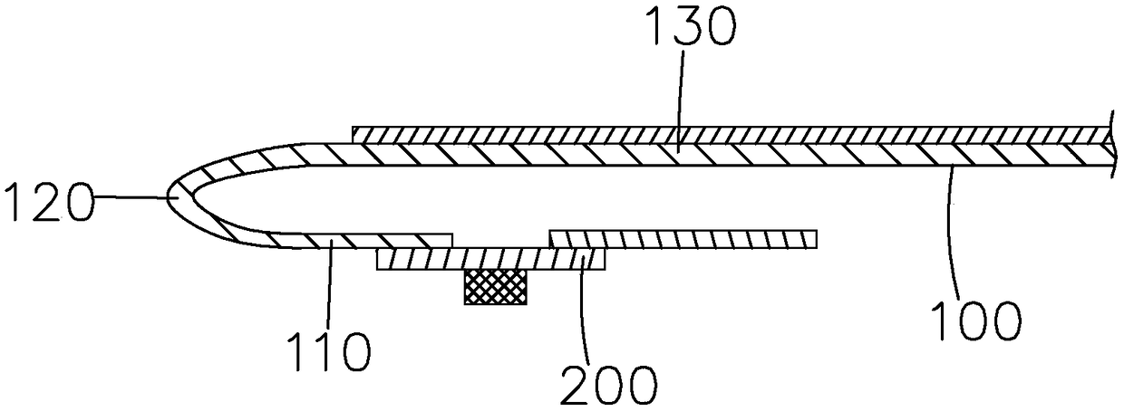
A flexible display device and flexible display technology, which are applied in the directions of identification devices, instruments, organic semiconductor devices, etc., can solve the problems of limiting the width of the binding area 110 at the lower end of the display panel, and the width of the display screen does not change much, etc. The effect of the resolution display

Active Publication Date: 2019-02-22
WUHAN CHINA STAR OPTOELECTRONICS SEMICON DISPLAY TECH CO LTD
View PDF7 Cites 26 Cited by
  • Summary
  • Abstract
  • Description
  • Claims
  • Application Information

AI Technical Summary

Problems solved by technology

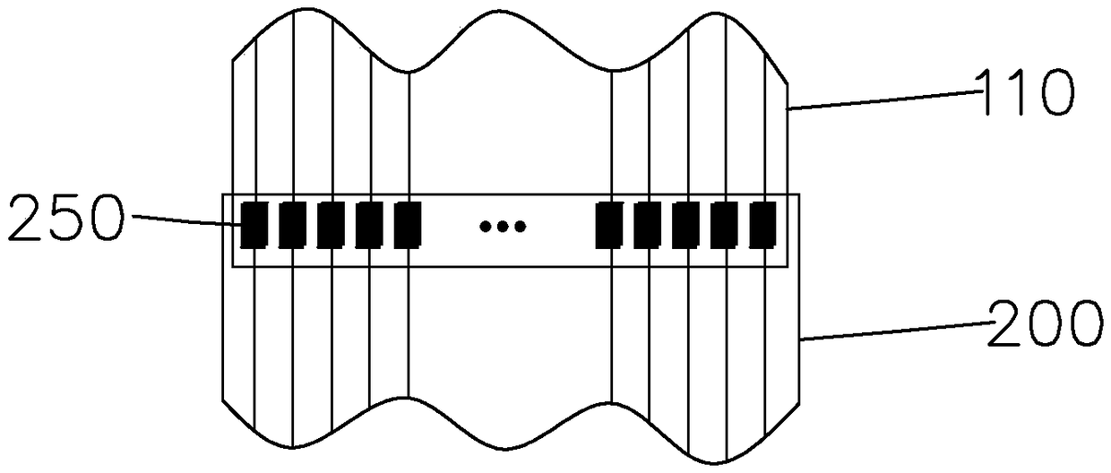
Specifically, such as image 3 As shown, during the binding process, the COF 200 realizes the binding through the one-to-one correspondence between the multiple connecting pins 250 set on the upper edge of the COF 200 and the multiple binding terminals set on the lowermost edge of the binding area 110. , in order to ensure the alignment accuracy of the bonding, the minimum bonding terminal spacing required to be reserved in the bonding area 110 is limited
Therefore, it can be predicted that as the resolution (PPI) of the display panel becomes higher and higher, the width requirement of the connection area between the binding area 110 and the COF200 at the lower end of the display panel becomes wider and wider. However, since the actual display screen width does not change much, the limitation The width of the binding area 110 at the lower end of the display panel

Method used


Image

  • Flexible display device
  • Flexible display device
  • Flexible display device

Examples


Embodiment Construction

[0036] In order to further illustrate the technical means adopted by the present invention and its effects, a detailed description is given below in conjunction with the preferred embodiments of the present invention and the accompanying drawings.

[0037] see Figure 4-5 The first embodiment of the flexible display device of the present invention includes a flexible display panel 1 , a chip on film 2 bound to the flexible display panel 1 , and a flexible circuit board 3 electrically connected with the chip on film 2 .

[0038] Specifically, the flexible display panel 1 is divided into a display area 11 , a binding area 12 located on one side of the display area 11 , and a bending area 13 located between the display area 11 and the binding area 12 .

[0039] Specifically, as Figure 7 As shown, the chip-on-film 2 includes a main body portion 21 and two expansion binding portions 22 vertically disposed at two ends of one side of the main body portion 21 respectively.

[0040]...


PUM


Abstract

The invention provides a flexible display device. The flexible display device comprises a flexible display panel and chip on film bound to the flexible display panel, the flexible display panel is divided into a display area, a binding area and a bending area, the chip on film comprises a main body part and two expansion binding parts vertically arranged at the two ends of one side edge of the main body part respectively, multiple connection pins are arranged on the side edge, adjacent to the two expansion binding parts, of the main body part and the two expansion binding parts, and the chip on film is bound to the binding area of the flexible display panel through the connection pins. The flexible display device has the advantages that by changing the shape of the chip on film, the two ends of one side of the main body part are additionally provided with the expansion binding parts, the edge of the side, only corresponding to the binding area, of existing chip on film is provided withthe connection pins, the edges of the three sides, corresponding to the binding area, of the existing chip on film are provided with the connection pins, under the situation of ensuring the binding precision and not increasing the width of the binding area, the number of the connection pins can be increased correspondingly, thereby being conductive to high-resolution-ratio display of the flexibledisplay device.

Description

technical field [0001] The present invention relates to the field of display technology, and in particular, to a flexible display device. Background technique [0002] Flat panel display devices on the existing market include Liquid Crystal Display (LCD) and Organic Light Emitting Diode (OLED) displays. Among them, OLED has many excellent characteristics such as self-luminescence, high brightness, wide viewing angle, high contrast, flexibility, low energy consumption, rich color, fast response and flexible screen preparation, which has aroused great interest in scientific research and industrial circles. The next-generation display technology, which is considered to be of great potential, has begun to gradually replace traditional liquid crystal displays, and is widely used in mobile phone screens, computer monitors, and full-color TVs. [0003] The existing flat panel display generally includes a display panel (Panel) and an external circuit. When the display panel is norm...

Claims


Application Information

Patent Timeline
Patent Type & Authority Applications(China)
IPC IPC(8): G09F9/30G09F9/33H01L27/32H10K99/00
CPCG09F9/301G09F9/33H10K59/12H10K59/80H05K2201/10128H05K1/028H05K1/147H05K1/189H05K3/365H05K2201/0154H05K2201/042H05K1/0281H05K2201/055H05K2201/053H05K2201/058H05K2201/09081H10K77/111H10K2102/311H10K50/80
Inventor 徐彬许红玉
Owner WUHAN CHINA STAR OPTOELECTRONICS SEMICON DISPLAY TECH CO LTD
Learn More