A smart home sensor control switch device and control method

A switch device and induction control technology, which is applied in the direction of program control, computer control, general control system, etc., to achieve good safety, meet the requirements of equipment use time, and avoid the effect of delay control

Active Publication Date: 2022-04-22
重庆忽米网络科技有限公司
View PDF10 Cites 0 Cited by
  • Summary
  • Abstract
  • Description
  • Claims
  • Application Information

AI Technical Summary

Problems solved by technology

And about this control switch device, there is no report yet

Method used


Image

  • A smart home sensor control switch device and control method
  • A smart home sensor control switch device and control method
  • A smart home sensor control switch device and control method

Examples


Embodiment 1

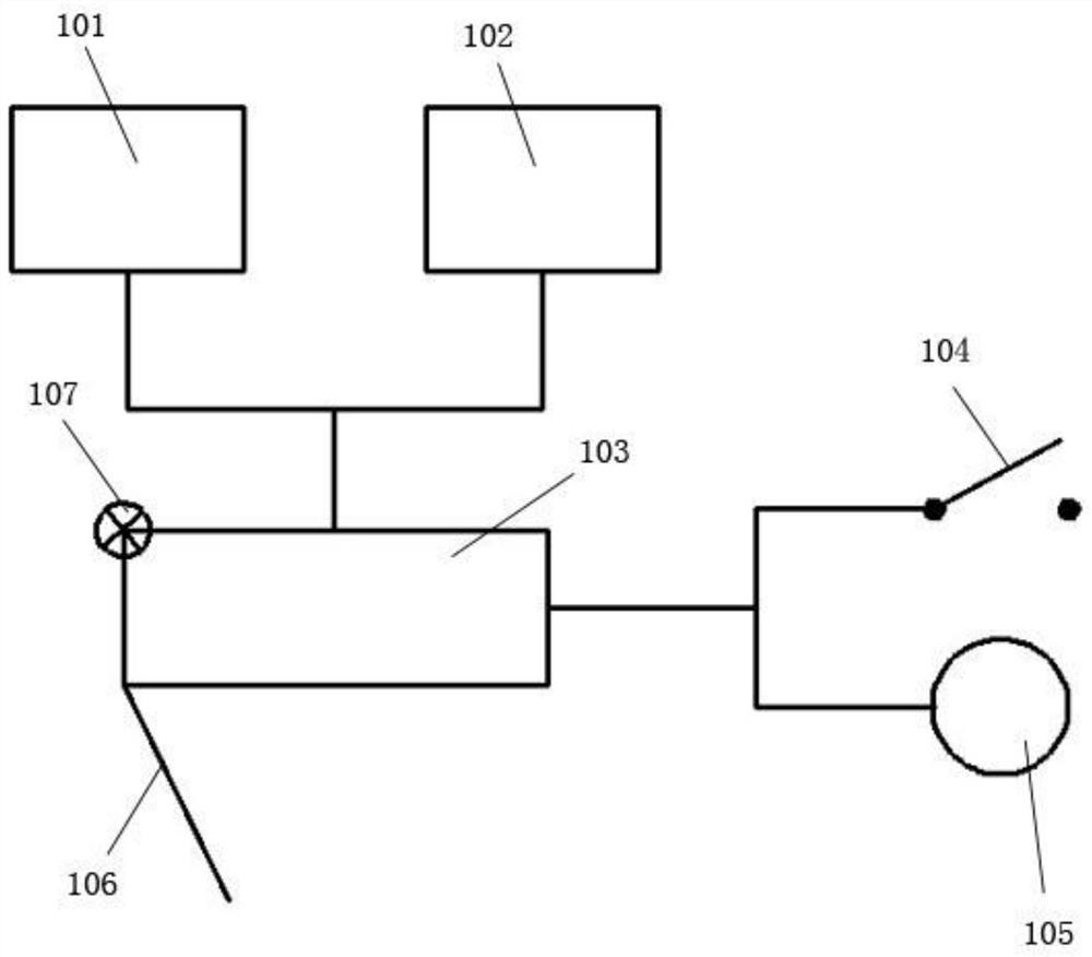
[0041] Please refer to figure 1 , figure 1It is a structural schematic diagram of a smart home sensor control switch 104 of the present invention. A smart home induction control switch device, characterized in that the switch 104 device includes a pressure sensor 101, a control board 103, a control program, a variable resistor 105, and a switch 104; the pressure sensor 101 and the gravity sensor 102 are both Establish a connection with the control board 103, and both the pressure sensor 101 and the gravity sensor 102 transmit the received data to the control board 103, and identify the data through the control program, and when the data detected by the pressure sensor 101 reaches the agreed threshold, send a control signal to the switch 104; when the data detected by the gravity sensor 102 reaches the agreed data mark, send a control signal to the variable resistor 105; the variable resistor 105 receives the control signal triggered by the gravity sensor 102, and changes the ...

Embodiment 2

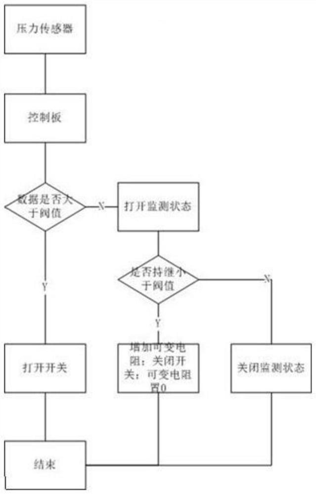
[0057] This embodiment is basically the same as Embodiment 1, the difference is that this embodiment provides a control method for a smart home sensor control switch device, please refer to figure 2 , figure 2 It is a schematic flow chart of using the pressure sensor 101 to control the state of the switch 104 . A control method for a smart home induction control switch device, the control method comprising the following steps:

[0058] Step S1, receiving pressure data through the pressure sensor 101, and opening or closing the switch 104 according to the pressure data and the predetermined threshold value;

[0059] Step S11, when the switch 104 is in the closed state, when the pressure sensor 101 receives the pressure data, transmits the pressure data to the control board 103, judges whether the pressure data is greater than the threshold through the control program, and when it is greater than the threshold, the control board 103 transmits a control signal to turn on the s...


PUM


Abstract

The invention relates to a smart home inductive control switch device and a control method. The switch device includes a pressure sensor, a control board, a control program, a variable resistor and a switch; the pressure sensor and the gravity sensor are both connected to the control board , and both the pressure sensor and the gravity sensor transmit the received data to the control board, and identify the data through the control program. When the data detected by the pressure sensor reaches the agreed threshold, a control signal is sent to the switch; when the data detected by the gravity sensor reaches the When the data identification is agreed, a control signal is sent to the variable resistor; the variable resistor receives the control signal triggered by the gravity sensor to change the resistance size; the switch receives the control signal triggered by the pressure sensor to open and close the switch. Its advantages are shown in: automatic control of the opening and closing of the switch, which satisfies the switch control in an automatic way, and also meets the user's requirements for the use time of the equipment.

Description

technical field [0001] The invention relates to the technical field of switch controllers for lamps, in particular to a smart home induction control switch device and a control method. Background technique [0002] With the development of science and technology, more and more smart homes have entered people's lives. In order to facilitate control, switch control devices are often installed on smart homes. [0003] Existing household lighting switch control devices include push-button control switches, voice-activated control switches, and remote control switches. Both push-button switches and remote-control switches require active operation by the user to control the switch, which brings inconvenience to work and life. At the same time, forgetting to turn off the switch due to human reasons will cause energy waste and pose a safety hazard; while the voice-activated switch Since the shutdown is automatically controlled by means of a delay, it cannot meet the user's requireme...

Claims


Application Information

Patent Timeline
Patent Type & Authority Patents(China)
IPC IPC(8): G05B19/042
CPCG05B19/0423G05B2219/25314
Inventor 巩书凯卢仁谦徐清华沈韬王巧
Owner 重庆忽米网络科技有限公司
Why Eureka
Try Eureka