A self-regulating heater

A heater and self-regulating technology, which is applied in heating methods, lighting and heating equipment, space heating and ventilation, etc. Ingenious structure to ensure the effect of normal use

Active Publication Date: 2021-07-30
聊城尚贤物资有限公司
View PDF0 Cites 0 Cited by
  • Summary
  • Abstract
  • Description
  • Claims
  • Application Information

AI Technical Summary

Problems solved by technology

[0005] The purpose of the present invention is to solve the problem that the heater without protection device in the prior art will fail after overheating and has potential safety hazards. The heater with protection device will automatically cut off power after overheating and cannot be automatically turned on after the temperature drops. The shortcomings of bringing inconvenience to users, and a self-regulating heater proposed

Method used


Image

  • A self-regulating heater
  • A self-regulating heater
  • A self-regulating heater

Examples


Embodiment 1

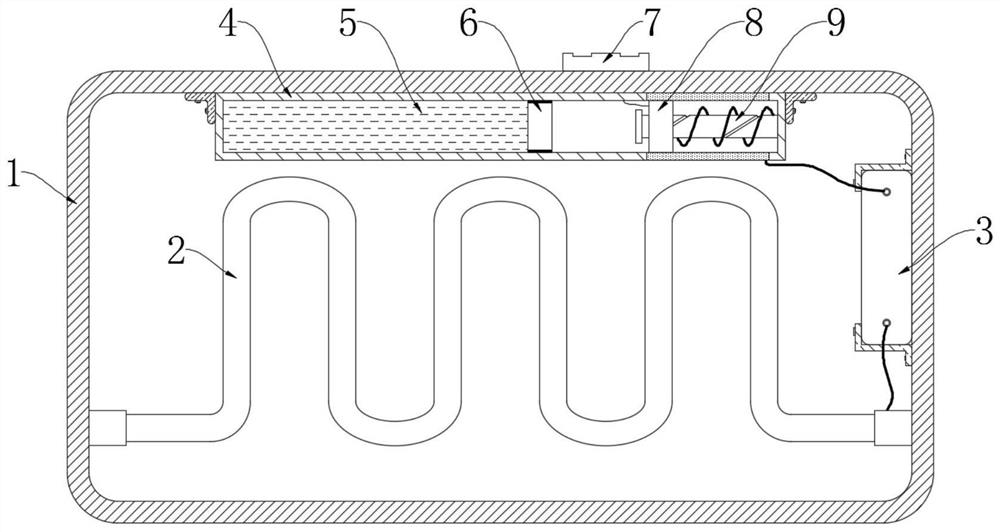
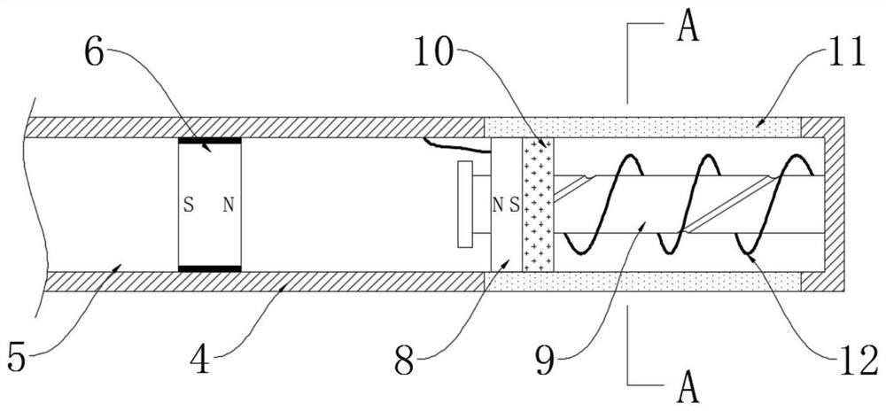
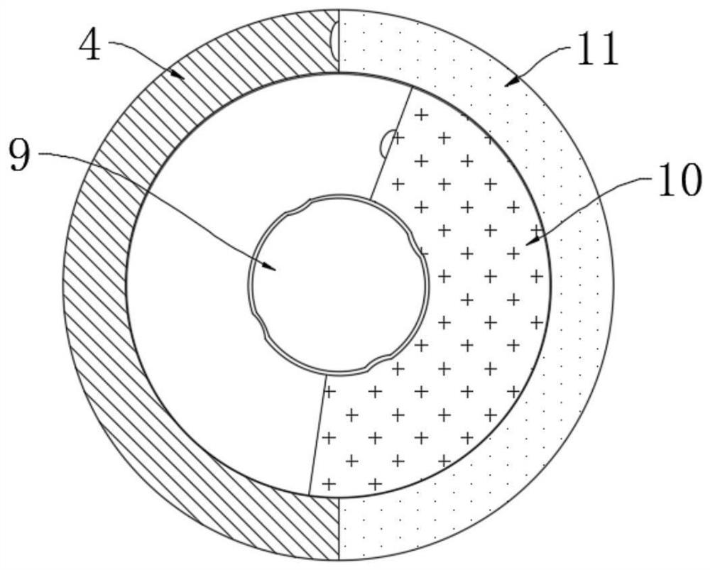
[0032] refer to Figure 1-4 , a self-regulating heater, including a shell 1 and a heating element 2 installed in the shell 1, the outer wall of the shell 1 is provided with an electrical connection element 7, which is used for plugging and connecting of supporting wires, the shell 1 is fixedly installed with a circuit board 3 and an assembly box 4, the circuit board 3 is electrically connected to the heating element 2, the current flowing through the heating element 2 and the voltage at both ends of the heating element 2 are controlled by the circuit board 3, and the side wall of the assembly box 4 An arc-shaped contact plate 11 is embedded, and the arc-shaped contact plate 11 is electrically connected to the circuit board 3 , a magnetic sliding plug 6 is arranged for sealing and sliding in the assembly box 4 , and a control mechanism is also provided in the assembly box 4 ;

[0033] The control mechanism includes a screw rod 9 fixedly welded on the inner wall of the assembly ...

Embodiment 2

[0044] refer to Figure 5-7 The difference between this embodiment and Embodiment 1 is that a circular sliding plug 13 is arranged for sealing and sliding in the assembly box 4, and a second elastic member is connected between the circular sliding plug 13 and the side wall of the assembly box 4 corresponding to the position. 14. The expansion fluid 5 is located between the magnetic slide 6 and the circular slide 13;

[0045] The side wall of the assembly box 4 is provided with a circulation port 17 and two limiting grooves 18, both of which are in communication with the circulation port 17 and located on the upper and lower sides of the circulation port 17 respectively. 18 is jointly slidably provided with a heat shield 16, and a heat exchange tank 1601 is provided on the heat shield 16, and the specification of the heat exchange tank 1601 matches the specification of the circulation port 17;

[0046] A communication piece 15 is provided between the upper limiting groove 18 a...


PUM


Abstract

The invention discloses a self-regulating heater, which comprises a casing and a heating element installed in the casing, the outer wall of the casing is provided with an electric connection element, and a circuit board and an assembly box are fixedly installed in the casing , the side wall of the assembly box is embedded with an arc-shaped contact sheet, and the arc-shaped contact sheet is electrically connected to the circuit board, a magnetic sliding plug is provided for sealing and sliding in the assembly box, and there is also a magnetic sliding plug in the assembly box. There is a control mechanism, and the control mechanism includes a screw rod fixedly welded on the inner wall of the assembly box, a magnetic slider is threaded on the screw rod, and an annular contact piece is embedded on the side of the magnetic slider away from the magnetic slider. The invention has an ingenious structure. On the premise of ensuring the safety of the device structure and the internal circuit, the heat generation of the heating element is automatically adjusted according to the ambient temperature, and when the temperature rises abnormally, the device can also automatically cut off the current in the circuit. The device will be turned on automatically without affecting people's use.

Description

technical field [0001] The invention relates to the technical field of household appliances, in particular to a self-regulating heater. Background technique [0002] In winter or in cold regions, people often use household heaters to increase the temperature in confined spaces. Compared with large heating equipment such as air conditioners and floor heating, small heaters are more convenient to move and less expensive. Users can also use small heating equipment Therefore, the use of small heaters greatly facilitates people's daily life. [0003] Common small heaters are mostly pure resistance heaters, such as electric heaters, heaters, etc. If people mistakenly place the heater in a corner with poor air flow and the switch is at a high position when moving a small heater, then After the heater works, not only the ambient temperature around the heater will rise rapidly, but also the internal heat cannot be transferred outward quickly. If the heater itself lacks protection de...

Claims


Application Information

Patent Timeline
Patent Type & Authority Patents(China)
IPC IPC(8): F24D13/02F24D19/06F24D19/10
CPCF24D13/02F24D19/062F24D19/1096
Inventor 于国飞黄宁宁
Owner 聊城尚贤物资有限公司
Why Eureka
Try Eureka