Electromagnetic wave sensing device and switch using the same

An induction device and electromagnetic wave technology, applied in the field of electromagnetic wave induction, can solve problems such as being susceptible to environmental interference, and achieve the effects of reducing potential safety hazards, reducing loss, and quantifying changes in signals.

Active Publication Date: 2019-02-22
SICHUAN UNIV +1
View PDF10 Cites 0 Cited by
  • Summary
  • Abstract
  • Description
  • Claims
  • Application Information

AI Technical Summary

Problems solved by technology

This scheme realizes communication without antenna, but this kind of communication is limited to short-distance communication and is easily disturbed by the environment

Method used


Image

  • Electromagnetic wave sensing device and switch using the same
  • Electromagnetic wave sensing device and switch using the same
  • Electromagnetic wave sensing device and switch using the same

Examples


Embodiment 1

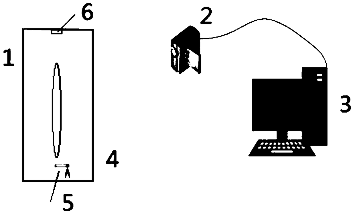
[0083] The top cover of the transparent cavity 4 is opened

[0084] When the electromagnetic radiation is turned on, the laminar flow height of the plume flow decreases, and the width of the plume flow increases significantly; when the electromagnetic radiation is turned off, the plume quickly returns to its initial height, and the results are as follows: Figure 6 shown. Figure 6 (a) is the plume flow before the electromagnetic radiation is turned on. Figure 6(b) shows the plume flow 1 second after turning on the radiation. Figure 6 (c) is the plume flow 2 seconds after turning off the radiation again. The white light beams are for lighting only. Figure 6 The red dot on the microwave leak detector in (b) indicates the presence of electromagnetic waves. The change of plume laminar height with time is as follows: Figure 8 As shown in (a), the x-axis and y-axis show time (s) and laminar flow height (cm), respectively. Significant changes are shown before the EM radiati...

Embodiment 2

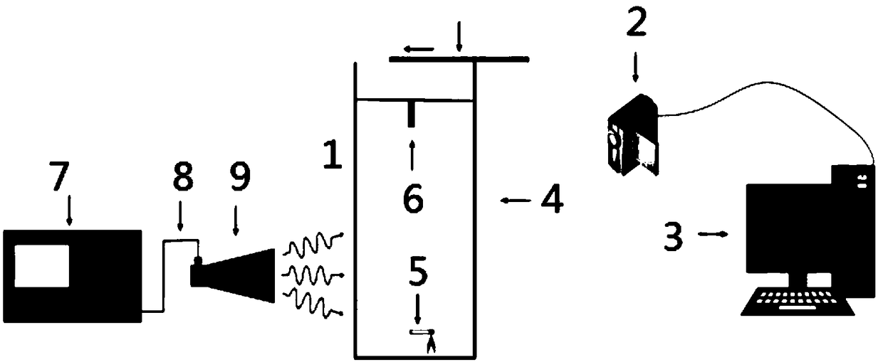
[0086] The top cover of the transparent cavity 4 is closed

[0087] When the top cover is closed, the experimental cavity 4 is completely closed. Weak flow field instabilities caused by the resulting concentration difference between the smoke and the surrounding air lead to weak disturbances in the plume, resulting in weak oscillations of the plume at the point where the original laminar flow was generated and entering the transition state of the plume flow. As the smoke continues to be produced, the concentration-related disturbances gradually decrease, and the plume airflow slowly returns to a stable laminar flow. When its flow state is stable, electromagnetic radiation is turned on, causing severe irregular oscillations in the plume flow and creating a turbulent state that is more easily maintained in the presence of electromagnetic waves. As in the previous experiments, the plume flow became very wide when the radiation was present, and quickly returned to its initial sta...


PUM


Abstract

The inventor of the invention has found that electromagnetic waves affect the rising form of smoke in air and thus provides an electromagnetic wave sensing device using smoke to replace an antenna anda switch using the same. The sensing of an electromagnetic wave signal is realized by smoke and the smoke replaces the antenna as a receiving device, so that the environment influence is eliminated.The electromagnetic wave sensing device can be applied to occasions with antenna limitation, so that the potential safety hazard caused by the antenna is reduced. The smoke can be identified by nakedeyes and signal transformation is read directly, so that visual induction of the electromagnetic wave signal is realized. Compared with the conventional electromagnetic wave sensing device, the novelelectromagnetic wave sensing device has the following advantages: the antenna as a receiving part is replaced by the smoke in an experiment cavity and the smoke serves as a s signal receiving device directly, so that the restriction by the antenna in the prior art is eliminated.

Description

technical field [0001] The invention belongs to the technical field of electromagnetic wave induction, and more specifically relates to an electromagnetic wave induction device and a switch using the device. Background technique [0002] Electromagnetic waves are oscillating particle waves derived from the same phase and mutually perpendicular electric fields and magnetic fields in space. They are electromagnetic fields that propagate in the form of waves and have wave-particle duality. Moving in space as waves. From low frequency to high frequency, electromagnetic radiation is mainly divided into: radio waves, microwaves, infrared rays, visible light, ultraviolet rays, X-rays and gamma rays. Radio waves are used for communication, etc. Microwaves are used for microwave ovens, satellite communications, etc. Infrared rays are used for remote control, thermal imagers, infrared guided missiles, etc. Visible light is the basis for most organisms to observe things, and ultraviol...

Claims


Application Information

Patent Timeline
Patent Type & Authority Applications(China)
IPC IPC(8): G01R29/08H03K17/95
CPCG01R29/08H03K17/9517H04B10/90
Inventor 杨晓庆敬衡吴诗月袁建平朱战霞
Owner SICHUAN UNIV
Why Eureka
Try Eureka