
Measuring device for aerodynamic parameters of engine flow field

A technology for aerodynamic parameters and measuring devices, applied in the field of aero-engines, can solve the problems of long consumption cycle, low precision, and increased measurement errors, and achieve the effects of improving measurement efficiency, improving efficiency, and reducing modification.

Active Publication Date: 2020-09-18
AECC SHENYANG ENGINE RES INST
View PDF6 Cites 0 Cited by
  • Summary
  • Abstract
  • Description
  • Claims
  • Application Information

AI Technical Summary

Problems solved by technology

[0003] At present, the commonly used fixed probes for total temperature, total pressure and static pressure measurement probes cannot adjust the angles of the measuring heads on the probes facing the incoming flow after installation, and when measuring the flow field parameters of certain sections in the engine test , the direction of the incoming flow will change greatly with the change of the engine state, and even exceed the direction insensitive angle range of the measuring sensor head, which will lead to an increase in the measurement error and cannot guarantee the accuracy of the flow field parameters in the engine test. accurate measurement
[0004] The positions of the total temperature, total pressure and static pressure measuring points of the external fixed probe are fixed, and the number of measuring points that can be arranged at the same time by a probe is limited, the flexibility is not high, and the efficiency is low. If you want to accurately measure the flow field For the parameter gradient distribution of a certain test section, it is necessary to simultaneously arrange multiple probes with different measuring points along the circumference for measurement, and multiple probes inserted at the same time will block the engine flow channel, resulting in distortion loss of the local flow field , so that the measured total temperature, total pressure and static pressure deviate from the true value, and the measurement accuracy is not high. At the same time, the installation of multiple probes also requires a large structural change of the engine, which takes a long time and costs a lot. When the static pressure hole is used to measure the static pressure of the flow channel, the measured value of the static pressure hole on the wall is generally approximated to the static pressure parameter value of the flow channel. The actual static pressure value has deviation, the accuracy is not high and the calibration is difficult
[0005] In the test, the fixed plug-in probe has to bear the high-temperature and high-speed gas flow in the engine flow channel, and the nearby rotating blades will also apply alternating loads to it. If the allowable strength or fatigue limit of the material of the probe support rod is exceeded , the failure of the strut may occur, threatening the safety of the engine test

Method used


Image

  • Measuring device for aerodynamic parameters of engine flow field
  • Measuring device for aerodynamic parameters of engine flow field
  • Measuring device for aerodynamic parameters of engine flow field

Examples


Embodiment Construction

[0024] The application will be further described in detail below in conjunction with the accompanying drawings and embodiments. It should be understood that the specific embodiments described here are only used to explain the related application, not to limit the application. In addition, it should be noted that, for ease of description, only parts relevant to the present application are shown in the drawings.

[0025] It should be noted that, in the case of no conflict, the embodiments in the present application and the features in the embodiments can be combined with each other. The present application will be described in detail below with reference to the accompanying drawings and embodiments.

[0026] In addition, it should be noted that in the description of this application, unless otherwise specified and limited, the terms "installation", "connection" and "connection" should be understood in a broad sense, for example, it can be a fixed connection or a It is a detach...


PUM


Abstract

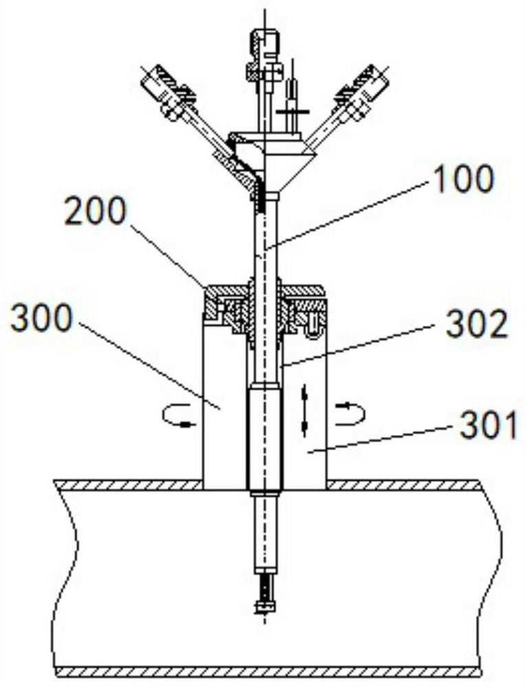
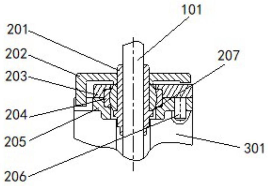
The invention provides an engine flow field aerodynamic parameter measuring device, which comprises a measuring assembly, a mounting assembly and a moving mechanism, wherein the measuring assembly comprises a probe strut; the moving mechanism comprises a mounting base, and a mounting hole is formed in the mounting base; the mounting assembly comprises a mounting bushing, a positioning mounting disc, an upper mounting disc, a radial spherical plain bearing, a lower mounting disc and a positioning pin, the mounting bushing sleeves the probe strut and is arranged in the mounting hole, and the lower mounting disc, the radial spherical plain bearing, the upper mounting disc and the positioning mounting disc sequentially sleeve the mounting bushing and are fixed to the mounting hole.

Description

technical field [0001] The present application relates to the technical field of aero-engines, and specifically provides a device for measuring aerodynamic parameters of an engine flow field. Background technique [0002] When measuring the total temperature, total pressure and static pressure parameters of the airflow in the engine flow field, the measuring sensor in the measuring device has direction sensitivity. Parameter measurement requires that the pressure-sensing hole of the measuring sensor head is parallel to the direction of the incoming flow, and the direction-insensitive angle range of various measuring sensors is limited. [0003] At present, the commonly used fixed probes for total temperature, total pressure and static pressure measurement probes cannot adjust the angles of the measuring heads on the probes facing the incoming flow after installation, and when measuring the flow field parameters of certain sections in the engine test , the direction of the i...

Claims


Application Information

Patent Timeline
Patent Type & Authority Patents(China)
IPC IPC(8): G01M15/00
CPCG01M15/00
Inventor 尹东陈晓明邹镇张灿隋洪伟
Owner AECC SHENYANG ENGINE RES INST
Learn More