
Cloth rack

A cloth and fixing rack technology, applied in the field of cloth racks, can solve the problem of not being able to slide freely, only one cloth reel can be installed, strengthening and other problems, so as to ensure the placement temperature, improve the sensitivity, and prevent the temperature from being too high or too low.

Pending Publication Date: 2019-02-22
阜阳鑫合服饰有限公司
View PDF1 Cites 1 Cited by
  • Summary
  • Abstract
  • Description
  • Claims
  • Application Information

AI Technical Summary

Problems solved by technology

Avoid affecting the quality of fabrics due to changes in storage environment and seasons. However, for some more expensive fabrics, the accuracy and sensitivity of temperature detection during storage need to be strengthened. Moreover, the fabric reel cannot slide freely, and only one fabric reel can be installed. For this reason, The invention proposes a cloth rack

Method used


Image

  • Cloth rack
  • Cloth rack
  • Cloth rack

Examples


Embodiment 1

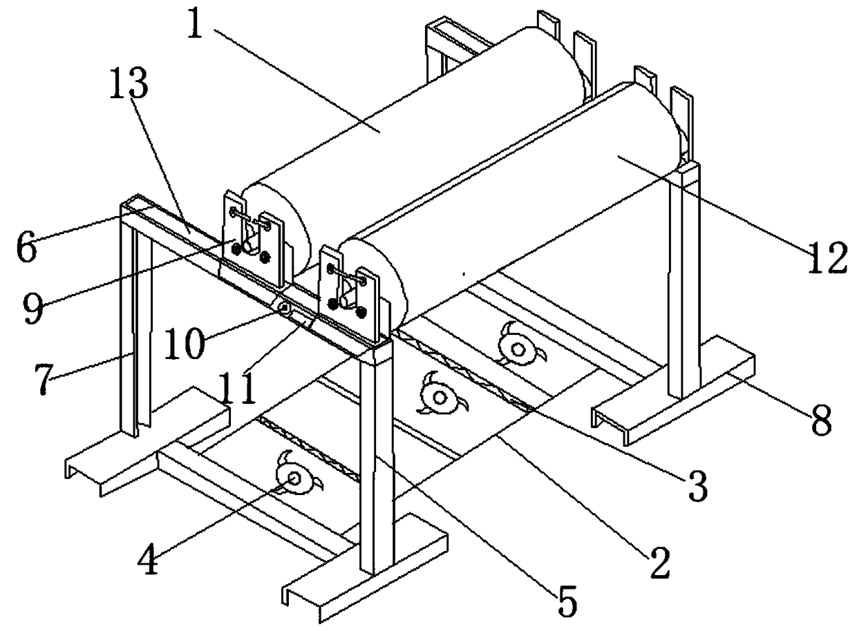
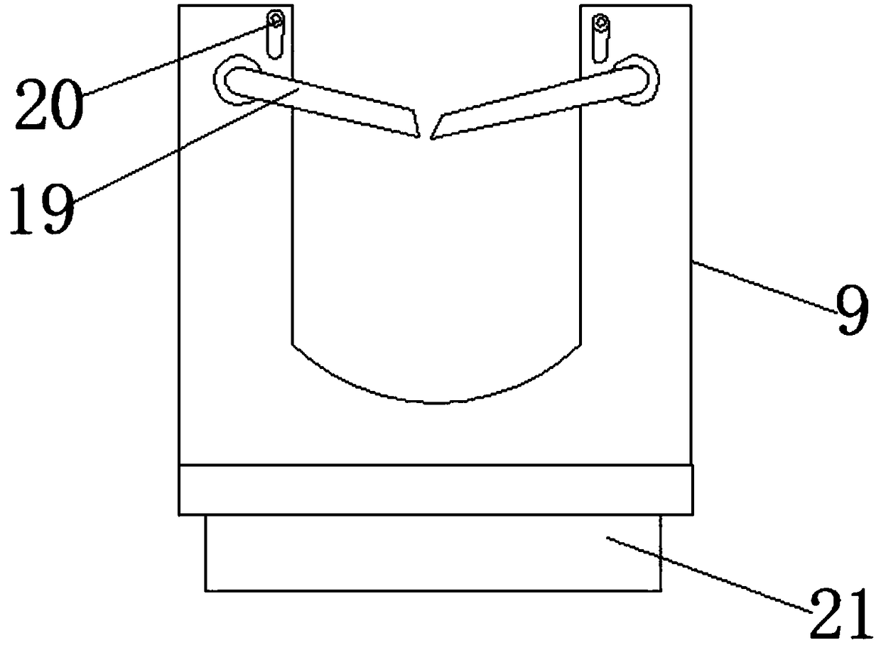
[0028] Such as Figure 1-4 As shown, a cloth rack includes a cloth rack main body 1, and the cloth rack main body 1 includes a base plate 2, a fan 4, a heating and cooling wire 3, a fixing frame 5 and a cloth reel 12, and two equidistant installations are arranged on the base plate 2 The heat radiation wire 3 is fixedly installed with a fan 4 on both sides of the heat radiation wire 3, and the interlayer of the substrate 2 is filled with water. Fixed vertical bar 7 is welded on the two ends of fixed horizontal bar 6, and I-shaped steel 8 is welded on the lower end of fixed vertical bar 7, and the upper surface of described fixed horizontal bar 6 is laid with slide rail 13, and described slide rail 13 is installed with Connecting frame 9, described connecting frame 9 comprises gear rod 19, fixed rod 20 and slide block 21, and the middle of described connecting frame 9 leaves groove, and the upper end both sides of groove is movably installed with gear rod 19, and described gear...

Embodiment 2

[0031] Such as Figure 1-4 As shown, a cloth rack includes a cloth rack main body 1, and the cloth rack main body 1 includes a base plate 2, a fan 4, a heating and cooling wire 3, a fixing frame 5 and a cloth reel 12, and two equidistant installations are arranged on the base plate 2 Heating the heat dissipation wire 3, and fans 4 are fixedly installed on both sides of the heating heat dissipation wire 3, and the interlayer of the substrate 2 is filled with water,

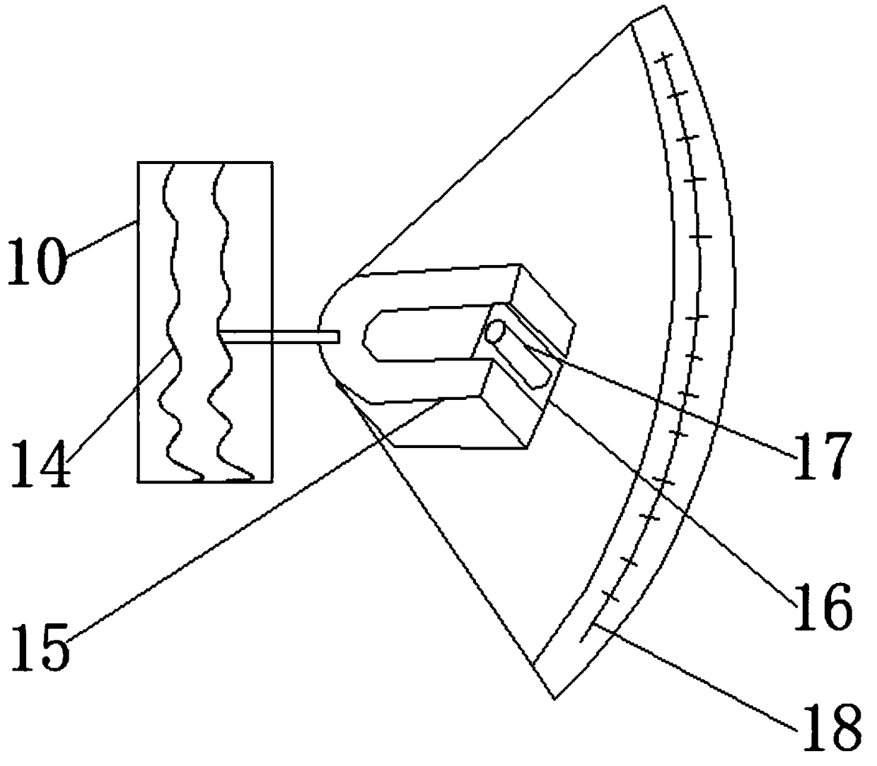
[0032] One side of the fixed frame 5 is fixed with a sensitive thermometer 10 at the middle position of the fixed crossbar 6, and one side of the sensitive thermometer 10 is fixedly equipped with a humidity sensor 11. By setting the sensitive thermometer 10, the temperature detection of the cloth rack can be improved. Sensitivity prevents the temperature of the cloth from being too high or too low, and more accurately guarantees the placement temperature of the cloth. The inside of the sensitive thermometer 10 is e...


PUM


Abstract

The invention discloses a cloth rack. A cloth rack body is included and comprises a base plate, fans, heating heat dissipation wires, fixing frames and cloth roll shafts. The two heating heat dissipation wires are arranged on the base plate at an equal interval. The fans are fixedly arranged on the two sides of the heating heat dissipation wires. The base plate is full of water. Each fixing framecomprises a fixing transverse rod, fixing vertical rods and joist steel, wherein the fixing vertical rods are welded to the two ends of the fixing transverse rod, and the joist steel is welded to thelower ends of the fixing vertical rods. The cloth roll shafts can slide on the fixing transverse rods through connecting frames, and a worker can conveniently adjust the distance between the two clothroll shafts according to the actual situation; through the arrangement of stop blocks, the connecting frames can be prevented from sliding out of sliding rails, the temperature detection sensitivityof the cloth rack can be improved, the placement temperature for cloth can be prevented from being too high or too low, the cloth placement temperature is more accurately guaranteed, and the cloth roll shafts can be fixed in grooves and can be prevented from sliding out during cloth rolling.

Description

technical field [0001] The invention relates to the technical field of cloth storage, in particular to a cloth rack. Background technique [0002] Cloth is a commonly used material in decorative materials. Including chemical fiber carpets, non-woven wall coverings, linen cloth, nylon cloth, colored tape, flannel and other fabrics. Cloth plays a considerable role in the decorative display, and is often the main force that cannot be ignored in the entire sales space. Extensive use of fabrics for wall decoration, partitions, and background treatment can also form a good commercial space display style. Fabrics are often placed on fabric racks for storage or display. [0003] Patent No. 201710919343.1 in the prior art discloses a cloth rack. Side plates for erecting cloth reels are arranged on both sides of the base plate. There are several grooves with louver fans on the base plate, and built-in fans, heating resistance wires and water respectively; According to the data fed ...

Claims


Application Information

Patent Timeline
Patent Type & Authority Applications(China)
IPC IPC(8): B65H18/02B65H18/08
CPCB65H18/02B65H18/08B65H2701/174
Inventor 黄祖运
Owner 阜阳鑫合服饰有限公司
Learn More