Method for calculating the cohesive force between horizontal layered surrounding rock layers of a simply supported beam structure

A calculation method and technology of simply supported beams, applied in calculation, design optimization/simulation, instruments, etc., can solve problems such as ignoring the interlayer cohesion of the roof rock mass, poor agreement between the model and the actual situation, and affecting construction costs and progress, etc. problems, to achieve the effect of simple and easy-to-understand models, reduce construction costs, and improve excavation progress

Active Publication Date: 2019-02-19
CHANGAN UNIV
View PDF3 Cites 0 Cited by
  • Summary
  • Abstract
  • Description
  • Claims
  • Application Information

AI Technical Summary

Problems solved by technology

Although some results have been obtained, the cohesion between the layers of the roof rock mass is generally ignored in the construction design, and the model at different stages of the construction is not in good agreement with the actual situation, which makes the calculation of the critical excavation span parameters in the tunnel construction and the actual construction There are large differences on site, which affects the construction cost and progress

Method used


Image

  • Method for calculating the cohesive force between horizontal layered surrounding rock layers of a simply supported beam structure
  • Method for calculating the cohesive force between horizontal layered surrounding rock layers of a simply supported beam structure
  • Method for calculating the cohesive force between horizontal layered surrounding rock layers of a simply supported beam structure

Examples


Embodiment Construction

[0038] In order to make the objects and advantages of the present invention clearer, the present invention will be further described in detail below in conjunction with the accompanying drawings and engineering examples. It should be understood that the specific embodiments described here are only used to explain the present invention, not to limit the present invention.

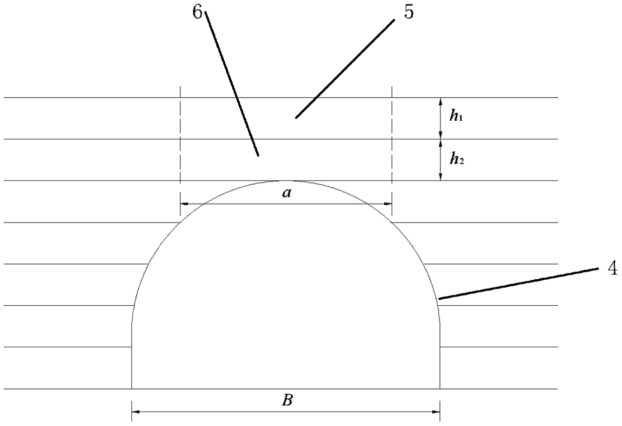
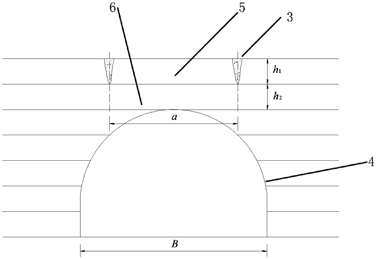
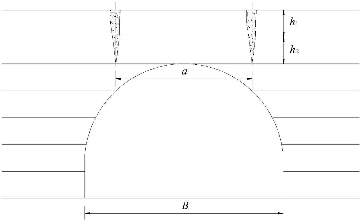
[0039] Figure 1-3 The schematic diagrams of the surrounding rock sections in the initial stage, intermediate stage, and later stage of tunnel excavation are given. 5 and 6 in the figure represent the upper rock mass and the lower rock mass respectively. Indicates the tunnel profile.

[0040] figure 1 In the initial stage of tunnel excavation, the surrounding rock is less disturbed, and the rock masses at both ends of the tunnel roof still have good integrity. At this time, the rock masses above the roof are constrained by the upper and lower strata It cannot be rotated, nor can it move up and down, left ...


PUM


Abstract

The invention discloses a method for calculating the cohesive force between horizontal layered surrounding rock layers of a simply supported beam structure, which equivalents the mechanics calculationmodel of the tunnel roof in different construction stages to the simply supported beam model after excavation disturbance, and simultaneously puts forward a calculation model of the cohesive force between horizontal layered surrounding rock layers and a concrete calculation formula of the cohesive force. By embedding the theoretical model of cohesive force between horizontally stratified surrounding rock layers into the traditional excavation width model, the critical excavation span of horizontal stratified surrounding rock tunnel is obtained, which is consistent with the actual construction, and is of great significance to guide the design and construction of horizontal stratified surrounding rock tunnel.

Description

technical field [0001] The invention belongs to the technical field of tunnel construction in civil engineering, and in particular relates to interlayer cohesion of simply supported beam structures in a method for calculating the safe excavation span of a tunnel roof in horizontal layered surrounding rock considering interlayer cohesion force calculation method. Background technique [0002] A layered rock mass is a type of sedimentary rock that has a layered structure. Layered rock masses are widely distributed in the world, accounting for about 66% of the total land area. my country's layered rock masses are distributed more widely, reaching 77% of the country's land area, mainly concentrated in the southwest, central China and northern Shaanxi. Due to the typical layered structure of layered rock mass, not only the deformation and strength properties have obvious anisotropy, but also the failure mechanism and mode of rock mass are obviously different from other rock mas...

Claims


Application Information

Patent Timeline
IPC IPC(8): G06F17/50
CPCG06F30/13G06F30/20
Inventor 罗彦斌陈建勋陈辉王利宝刘伟赵毅
Owner CHANGAN UNIV
Why Eureka
Try Eureka