
Ocean sonar imaging device and using method thereof

An imaging device and sonar technology, which is applied to measurement devices, uses re-radiation, and re-radiation of sound waves, etc., can solve the problems of single sonar function and cannot perform live shooting, and achieve the effect of improving accuracy.

Inactive Publication Date: 2019-02-19
TANGSHAN HARBIN SHIP TECH CO LTD +1
View PDF0 Cites 4 Cited by
  • Summary
  • Abstract
  • Description
  • Claims
  • Application Information

AI Technical Summary

Problems solved by technology

[0003] The existing sonar has a single function and can only perform underwater detection to know the underwater terrain and the location of creatures, but it cannot perform live shooting and understand clear scenes

Method used


Image

  • Ocean sonar imaging device and using method thereof
  • Ocean sonar imaging device and using method thereof
  • Ocean sonar imaging device and using method thereof

Examples


Embodiment 1

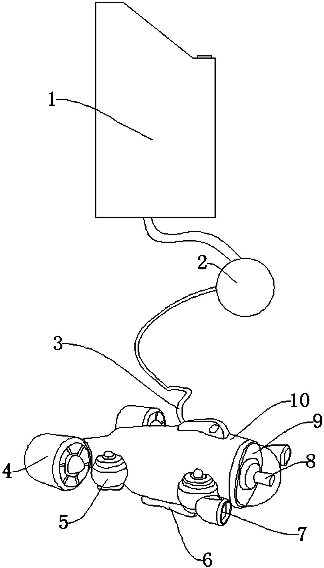
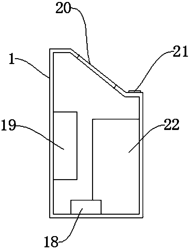
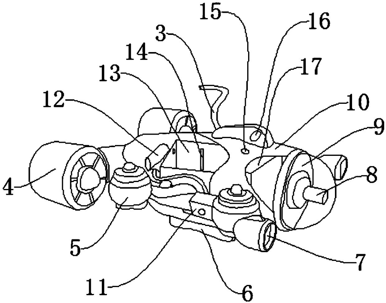
[0031] Such as Figure 1-Figure 6As shown, a marine sonar imaging device includes an underwater host 1 and a waterproof casing 10. A display screen 20 is provided on the front surface of the underwater host 1, and a remote control button 21 is provided on the lower side of the display screen 20. The underwater host 1 is internally provided with a digital signal processor 19 and a data memory 22, the model of the digital signal processor 19 is TMS320C6748BZCE, the lower end of the underwater host 1 is provided with an optical fiber data receiver 18, and the optical fiber data receiver 18 is provided with a connection cable 3, the connection cable 3 is provided with a hoist 2, the other end of the connection cable 3 is provided with the waterproof casing 10, and the rear end of the waterproof casing 10 is provided with After the propeller 4, the front and rear sides of the waterproof casing 10 are provided with air compression chambers 5, and there are four air compression chamb...

Embodiment 2

[0033] The difference between this embodiment and Embodiment 1 is:

[0034] In this embodiment, the underwater lighting lamp 7 is fixed on both sides of the front of the waterproof housing 10 by screws, and the underwater lighting lamp 7 is a high spotlight LED lamp.

[0035] Specifically, such setting can provide underwater lighting, which is convenient for taking pictures.

[0036] The present invention also provides a method for using a marine sonar imaging device, which is applied to the above-mentioned marine sonar imaging device. The waterproof casing 10 is lowered into the water through the winch 2, and the remote control button 21 is used to control the remote control button. 21 starts, the water in and out control valve 11 is opened, and the external seawater can be pumped into the water storage bin 13 to increase its weight and make it sink into the water. When the water pump 12 pumps water into the water storage bin 13, the water storage bin The air of 13 is inhale...


PUM


Abstract

The invention discloses an ocean sonar imaging device and a using method thereof, and the device comprises an underwater host and a waterproof casing. A display screen is disposed on the front surfaceof the underwater host. A remote control button is disposed on the lower side of the display screen. A digital signal processor and a data memory are disposed inside the underwater host. A fiber optic data receiver is disposed at the lower end of the underwater host. A connection cable is disposed on the optical fiber data receiver. A hoist is disposed on the connection cable. A waterproof casingis disposed at the other end of the connection cable. A rear thruster is disposed on both sides of the rear end of the waterproof casing. The beneficial effects of the ocean sonar imaging device andthe using method thereof are as follows: 1. the detection is performed by dragging and dropping, or by active moving, so the accuracy of the detection is improved; 2. the comparison may be performed with biological information stored in the data memory to conveniently and quickly analyze the underwater biological information; 3. the underwater scene can be photographed or recorded by taking pictures to facilitate a clear understanding of the underwater situation.

Description

technical field [0001] The invention relates to the technical field of sonar, in particular to a marine sonar imaging device and a method for using the same. Background technique [0002] Sonar is the transliteration of the English abbreviation "SONAR". Its full name in Chinese is: Sound Navigation and Ranging. equipment. It has two types, active and passive, and belongs to the category of acoustic positioning. Sonar is an electronic device that uses sound waves in water to detect, locate and communicate underwater targets. It is the most widely used and most important device in underwater acoustics. [0003] Existing sonar has a single function and can only perform underwater detection to know the underwater topography and the location of creatures, but it cannot perform live shooting and understand clear scenes. Contents of the invention [0004] The object of the present invention is to provide a marine sonar imaging device and its usage method in order to solve the ...

Claims


Application Information

Patent Timeline
Patent Type & Authority Applications(China)
IPC IPC(8): G01S15/89G01S7/521H04N7/18
CPCG01S15/89G01S7/521H04N7/18
Inventor 王福斌吴宝江张怡刘浩源吴金秋郑瑞云孙立晶田丙奇曹佳学
Owner TANGSHAN HARBIN SHIP TECH CO LTD
Learn More