Gear manufacturing equipment with illuminating function

A gear manufacturing and equipment technology, applied in the field of gear manufacturing equipment, can solve the problems of increasing equipment complexity, cumbersome blank gear clamping steps, large power source consumption for polishing equipment, etc., achieves high use and promotion value, facilitates polishing work, Simple and convenient working steps

Inactive Publication Date: 2019-02-19
NINGBO ZHUXING MACHINERY DESIGN
View PDF0 Cites 2 Cited by
  • Summary
  • Abstract
  • Description
  • Claims
  • Application Information

AI Technical Summary

Problems solved by technology

[0002] Gears refer to the mechanical elements with gears on the wheel rim that continuously mesh to transmit motion and power. When manufacturing rough gears, they need to be polished. Before polishing the rough gears, the rough gears need to be clamped and stabilized. At present The clamping steps of the rough gear are cumbersome, and after the clamping is completed, the gear is usually rotated by the polishing equipment to polish the gear. The overall rotation of the polishing equipment requires a large amount of power source and increases the complexity of the equipment. Therefore, a Gear processing and manufacturing equipment that can conveniently clamp and rotate blank gears

Method used


Image

  • Gear manufacturing equipment with illuminating function
  • Gear manufacturing equipment with illuminating function
  • Gear manufacturing equipment with illuminating function

Examples


Embodiment Construction

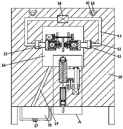
[0015] Combine below Figure 1-3 The present invention is described in detail, and for convenience of description, the orientations mentioned below are now stipulated as follows: figure 1 The up, down, left, right, front and back directions of the projection relationship itself are the same.

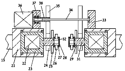
[0016] refer to Figure 1-3 According to an embodiment of the present invention, a gear manufacturing equipment with lighting function includes a manufacturing body 10, a manufacturing cavity 16 is provided in the manufacturing body 10, and a clamping assembly is installed in the manufacturing cavity 16, so The clamping assembly includes a sliding rod 15 symmetrically slidingly installed on the left and right side walls of the manufacturing cavity 16, and a first sliding chamber 12 is symmetrically arranged in the manufacturing body 10 outside the sliding rod 15, The first piston block 11 fixedly connected with the push slide rod 15 is slidably installed in the first sliding chamber 12...


PUM


Abstract

The invention discloses gear manufacturing equipment with an illuminating function. The gear manufacturing equipment with the illuminating function comprises a manufacturing equipment body, a manufacturing cavity is formed in the manufacturing equipment body, and a clamping assembly is installed in the manufacturing cavity; the clamping assembly comprises pushing sliding rods which are slidably installed on the left side wall and the right side wall of the manufacturing cavity in a bilateral symmetry mode, first sliding cavities are formed in the portions, on the outer sides of the pushing sliding rods, of the interior of the manufacturing equipment body in a bilateral symmetry mode, and first piston blocks fixedly connected with the pushing sliding rods are slidably installed in the firstsliding cavities; and first air pressure cavities are formed in the outer side walls of the first sliding cavities in a communicating mode, the left first air pressure cavity and the right first airpressure cavity are in power connection with a first air pressure cylinder, and the first air pressure cylinder is fixedly installed in the manufacturing equipment body. According to the gear manufacturing equipment, a gear can be quickly and conveniently clamped between abutting plates on the left side and the right side, the clamped gear can be effectively controlled to rotate, then polishing work can be conveniently conducted on the gear, the working steps are simple and convenient to operate, and the high usage and popularization value is achieved.

Description

technical field [0001] The invention relates to the technical field of gear processing, in particular to gear manufacturing equipment with lighting function. Background technique [0002] Gears refer to the mechanical elements with gears on the wheel rim that continuously mesh to transmit motion and power. When manufacturing rough gears, they need to be polished. Before polishing the rough gears, the rough gears need to be clamped and stabilized. At present The clamping steps of the rough gear are cumbersome, and after the clamping is completed, the gear is usually rotated by the polishing equipment to polish the gear. The overall rotation of the polishing equipment requires a large amount of power source and increases the complexity of the equipment. Therefore, a Gear processing and manufacturing equipment that can conveniently clamp and rotate blank gears. Contents of the invention [0003] The object of the present invention is to provide a gear manufacturing equipment...

Claims


Application Information

Patent Timeline
Patent Type & Authority Applications(China)
IPC IPC(8): B24B19/00B24B55/06B24B41/06B24B55/00
CPCB24B19/00B24B41/06B24B55/00B24B55/06
Inventor 叶君尧
Owner NINGBO ZHUXING MACHINERY DESIGN
Why Eureka
Try Eureka