


Quick Research
Generate reliable direction feasibility study reports for your R&D in just a few steps.

Technical Q&A
Discover and master advanced knowledge NOW. Basics, ideas, possibilities, all at once.

Find Solutions
As an expert in R&D theories, this can generate solutions to your technical problems instantly.

Evaluate Feasibility
Analyze your overall solution with one click, know your potential R&D risks in advance.

Monitor Landscape
Get weekly tech updates, stay abreast of the latest tech innovations and key insights.
An earphone wire take-up device and an earphone using the wire take-up device
A technology of cable take-up and earphones, which is applied in the direction of earphone cable/cable storage, earpiece/earphone accessories, special tools for hearing equipment, etc. Effects of cleaning, increasing service life, and preventing wire shrinkage
- Summary
- Abstract
- Description
- Claims
- Application Information
AI Technical Summary
Problems solved by technology
Method used
Image

Examples
Embodiment 1
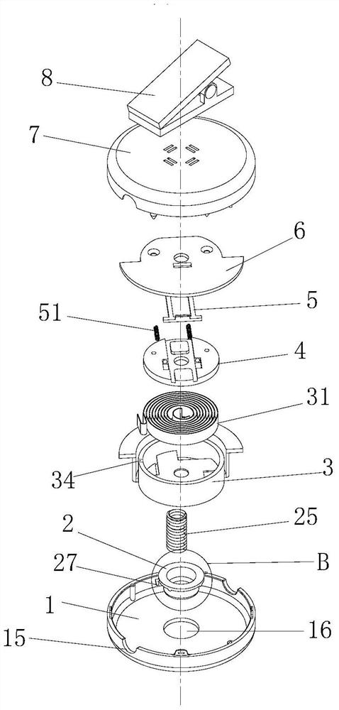
[0042] Such as figure 2 As shown, the earphone cable take-up device of this embodiment includes a disc-shaped upper cover 1, a disc-shaped lower cover 7, a spring seat 3, a stop cover 2, a scroll spring 31, a slider gland 6, and a scroll spring cover 4 And slide block 5 that can slide and reset.
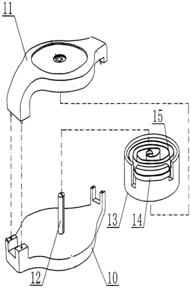
[0043] Such as Figure 4 As shown, the anti-rotation cover 2 is set in the shape of a top hat, such as Pic 4-1 As shown, the lower edge 26 of the anti-rotation cover is also provided with two L-shaped anti-rotation cover buckles 27 obliquely. One end of the L-shaped anti-rotation cover buckle 27 is vertically connected with the anti-rotation cover 2 to form a vertical end, and the other end is arranged obliquely to form a vertical end. sloped ends.
[0044] Such as Figure 5 to Figure 7 As shown, the spring seat 3 is arranged in a ring shape, and the outside of the side wall of the spring seat 3, the disc-shaped upper cover 1 and / or the disc-shaped lower cover 7 is coated with ...
Embodiment 2
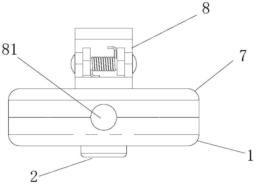
[0052] The working method of the earphone wire take-up device of the present invention, as Figure 13 shown, including the following steps:
[0053] A. The wire 9 enters the cavity from the wire inlet end 81 , coils on the outside of the side wall of the annular spring seat 3 , and passes through the wire outlet end 82 ; the pressing part 55 of the slider 5 compresses the wire 9 .
[0054] B. When the length of the wire needs to be adjusted, push the slider 5 so that the pressing part 55 of the slider 5 is away from the wire 9, and pull the wire out along the outlet end 82. At this time, the inclined end of the L-shaped anti-rotation cover buckle 27 will be The elastic retainer 32 is lifted to make the elastic retainer 32 pass through the L-shaped stop cover buckle 27 smoothly, the spring seat 3 rotates, the scroll spring 31 is deformed, and the wire 9 is pulled out.
[0055] C. After the wire is pulled out to the required distance, the slider 5 is released, and the slider 5 ...
Embodiment 3
[0058] An earphone using the wire take-up device of the above-mentioned embodiment 1 or 2, the wire is an earphone wire of the earphone. The earphone is an earphone for a radio, a mobile phone or a computer. One end of the earphone line is connected with a plug, and the other end is provided with two or one loudspeaker.
[0059] The earphone is an earphone, an earhook or a headset. In terms of driving mode, the earphones can be dynamic earphones, moving iron earphones, isomagnetic earphones, electrostatic earphones or electret earphones.
PUM
 Abstract
Description
Claims
Application Information
 - R&D Engineer
- R&D Manager
- IP Professional
- Industry Leading Data Capabilities
- Powerful AI technology
- Patent DNA Extraction
Browse by: Latest US Patents, China's latest patents, Technical Efficacy Thesaurus, Application Domain, Technology Topic, Popular Technical Reports.
© 2024 PatSnap. All rights reserved.Legal|Privacy policy|Modern Slavery Act Transparency Statement|Sitemap|About US| Contact US: help@patsnap.com