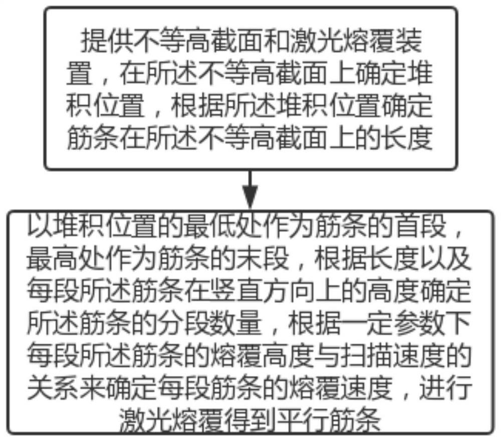
Laser cladding method for stacking horizontal ribs on unequal height sections
A technology of laser cladding and horizontal ribs, applied in laser welding equipment, improving energy efficiency, improving process efficiency, etc., can solve problems such as insufficient strength, welding deformation, long casting cycle, etc., and achieve accumulation rate and material utilization rate High, high parallelism, firm rib structure
- Summary
- Abstract
- Description
- Claims
- Application Information
AI Technical Summary
Problems solved by technology
Method used
Image


Examples
Embodiment 1
[0032] See figure 2 , the stacking positions of the ribs in this embodiment include planes and slopes. Specifically, the total length of the ribs is 34.4mm, the length on the plane is 10mm, and the length on the slope is 24.4mm; The projected length is 5.37mm. The number of rib segments is determined according to the above content, and the height difference between adjacent ribs must be less than or equal to 0.5mm. Wherein, sin α=5.37 / 25=0.2148, cos α=0.9767, as can be seen from the above formula, the number of rib segments in this embodiment is The present embodiment takes n=14, wherein, rib 2 is the first section, rib 13 is the end (planar section), rib 1 and 14 are the deceleration sections on the first section and the end respectively, and the length of the deceleration section is 1mm. Then determine the cladding height of each rib according to the actual needs, and then determine the cladding speed of each rib according to the relationship between cladding height and c...
Embodiment 2
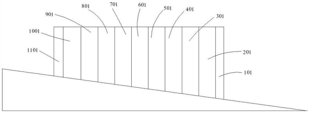
[0037] See image 3 , the stacking position of ribs in this embodiment is only on the slope,
[0038] In this embodiment, laser cladding is used to accumulate horizontal ribs only on the slope. Specifically: the angle between the slope and the horizontal line is 9°, determine the length of the stacking position, that is, the length of the rib is 30mm, and determine the number of rib segments according to the above content , the height difference between adjacent ribs must be less than or equal to 0.5mm. It can be seen from the above formula that the number of rib segments in this embodiment is In this embodiment, n=11, wherein the rib 201 is the first section, the rib 1001 is the end, and the ribs 101 and 1101 are the deceleration sections arranged on the first section and the last section respectively, and the length of the deceleration section is 1 mm. Then determine the cladding height of each rib according to actual needs, and then determine the cladding speed of each r...
PUM
 Abstract
Description
Claims
Application Information
 - R&D
- Intellectual Property
- Life Sciences
- Materials
- Tech Scout
- Unparalleled Data Quality
- Higher Quality Content
- 60% Fewer Hallucinations
Browse by: Latest US Patents, China's latest patents, Technical Efficacy Thesaurus, Application Domain, Technology Topic, Popular Technical Reports.
© 2025 PatSnap. All rights reserved.Legal|Privacy policy|Modern Slavery Act Transparency Statement|Sitemap|About US| Contact US: help@patsnap.com