
Antenna with adjustable wave width

An antenna, straight-line technology, applied in the field of antennas with adjustable bandwidth, can solve problems such as difficulty in meeting the needs of different coverage scenarios, and achieve the effect of switching

Active Publication Date: 2019-02-15
COMBA RF TECH GUANGZHOU LTD +1
View PDF7 Cites 1 Cited by
  • Summary
  • Abstract
  • Description
  • Claims
  • Application Information

AI Technical Summary

Problems solved by technology

[0003] During the implementation process, the inventor found at least the following problems in the traditional technology: the vertical beam width of the traditional antenna is fixed, and the corresponding coverage area is also relatively fixed, which makes it difficult to meet the needs of different coverage scenarios

Method used


Image

  • Antenna with adjustable wave width
  • Antenna with adjustable wave width
  • Antenna with adjustable wave width

Examples


Embodiment Construction

[0032] In order to facilitate the understanding of the present application, the present application will be described more fully below with reference to the relevant drawings. A preferred embodiment of the application is shown in the drawings. However, the present application can be embodied in many different forms and is not limited to the embodiments described herein. On the contrary, the purpose of providing these embodiments is to make the disclosure of this application more thorough and comprehensive.

[0033] Unless otherwise defined, all technical and scientific terms used herein have the same meaning as commonly understood by one of ordinary skill in the technical field of the invention. The terms used herein in the description of the present invention are for the purpose of describing specific embodiments only, and are not intended to limit the present invention. As used herein, the term "and / or" includes any and all combinations of one or more of the associated lis...


PUM


Abstract

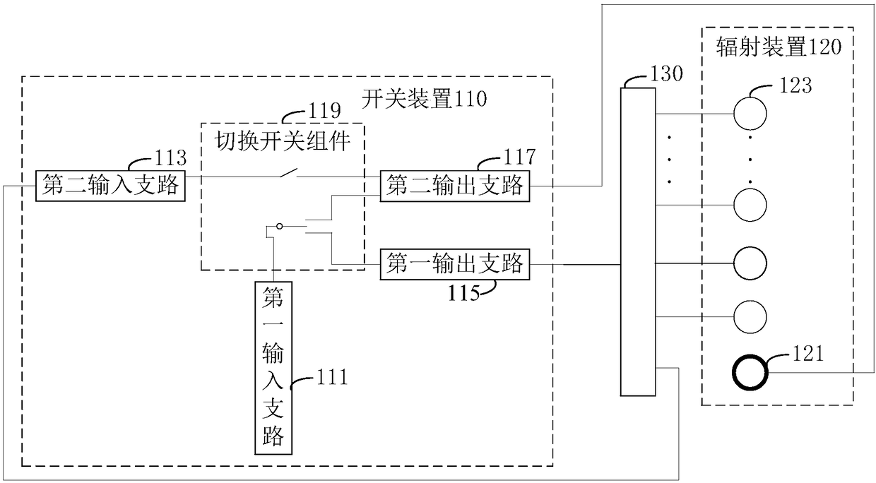
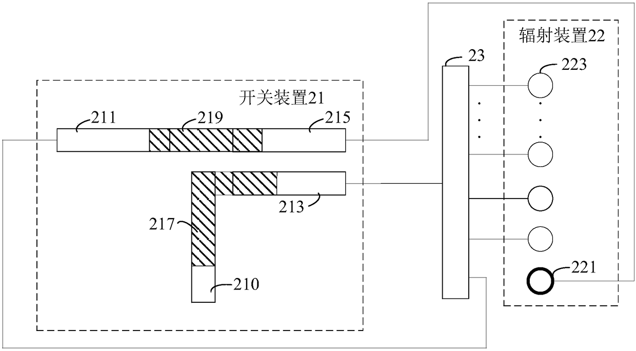
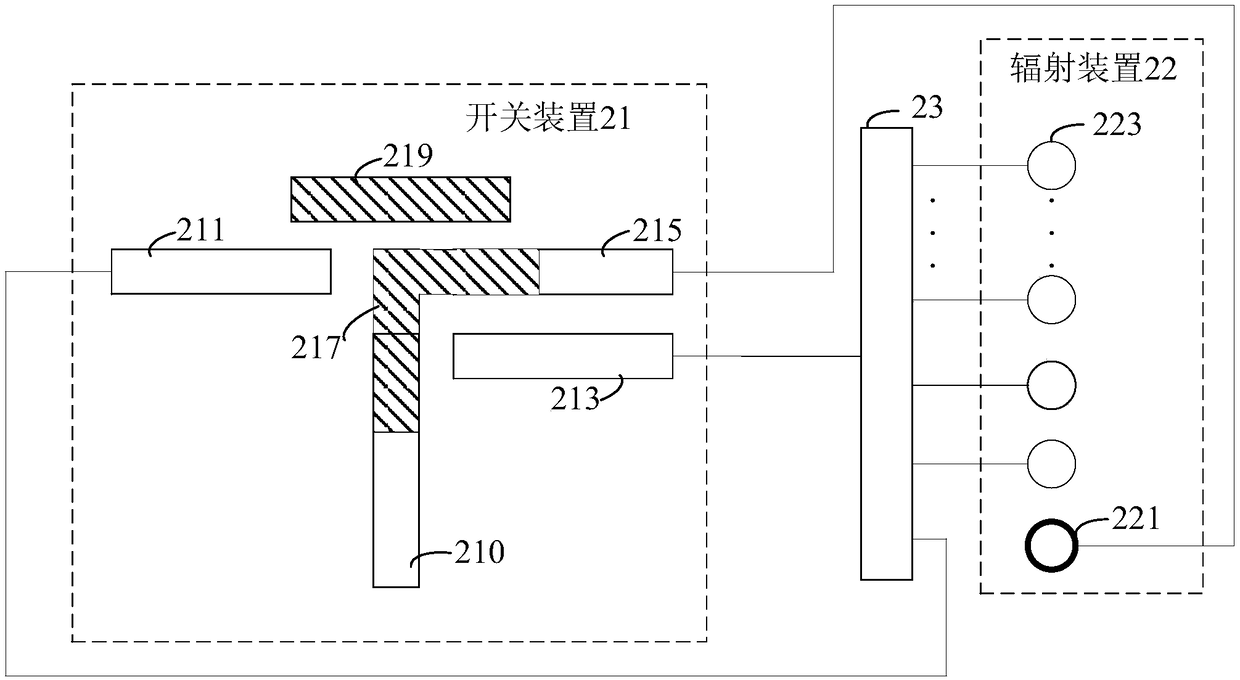
The invention discloses an antenna with an adjustable wave width. The antenna comprises a switch device, a radiation device and a phase shifter; the switch device comprises a first input branch, a second input branch, a first output branch, a second output branch and a switching switch component; the radiation device comprises a first radiation unit and a plurality of second radiation units; eachsecond phase-shifting output port is connected with each second radiation unit in a one-to-one correspondence mode; the output port of the first output branch is connected with the input port of the phase shifter, and the input port is connected with the output port of the first input branch through the switching switch component; the output port of the second output branch is connected with the first radiation unit, and the input port is connected with the output port of the second input branch through the switching switch component; the input port of the second input branch is connected witha first phase-shifting output port; and the output port of the first input branch is connected with the input port of the second output branch through a switching switch component. Therefore, the beam width of the antenna vertical plane can be changed, and the requirements of different coverage scenes can be met.

Description

technical field [0001] The invention relates to the technical field of antennas, in particular to an antenna with adjustable wave width. Background technique [0002] With the development of mobile communication, in order to meet the coverage and capacity requirements of antennas, adding sites has become an inevitable choice. After the large-scale construction of macro base stations, in-depth coverage and blind coverage in residential areas and commercial streets have become the focus of major operators. The cost of adding traditional macro stations in these areas is high, and the antenna size is large. address is difficult. At present, micro-station antennas or low-gain directional antennas are often used for coverage or blind filling. [0003] During the implementation process, the inventor found at least the following problems in the traditional technology: the vertical beam width of the traditional antenna is fixed, and the corresponding coverage area is also relativel...

Claims


Application Information

Patent Timeline
IPC IPC(8): H01Q1/50H01Q21/29
CPCH01Q1/50H01Q21/29
Inventor 苏国生赖展军吴庚飞法斌斌李明超李学锋刘培涛
Owner COMBA RF TECH GUANGZHOU LTD
Learn More