Novel worm gear type speed changer and speed changing method thereof
A transmission and worm gear technology, applied in the direction of gear transmission, belt/chain/gear, transmission parts, etc., can solve the problems of high cost, large occupied volume, complex transmission structure, etc., and achieve the goal of reducing volume and increasing transmission speed Effect
- Summary
- Abstract
- Description
- Claims
- Application Information
AI Technical Summary
Problems solved by technology
Method used
Image
Examples
Embodiment 1
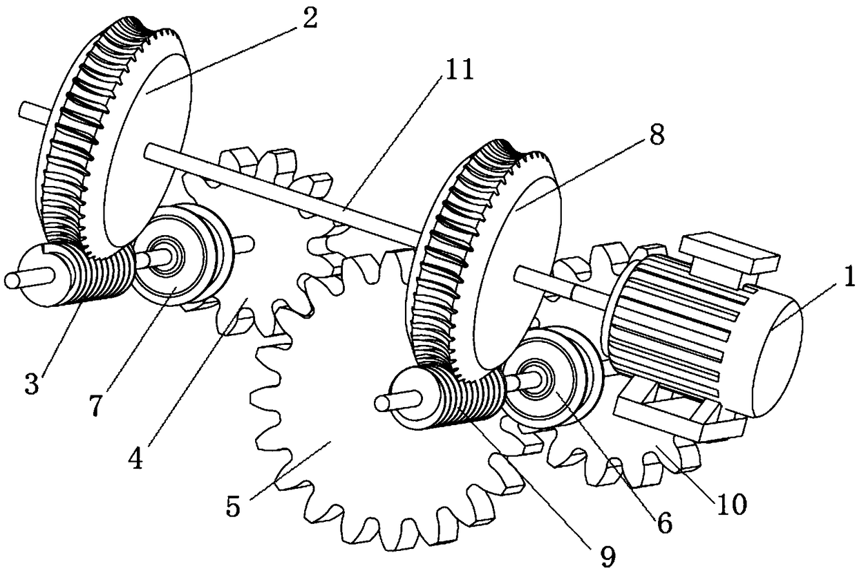
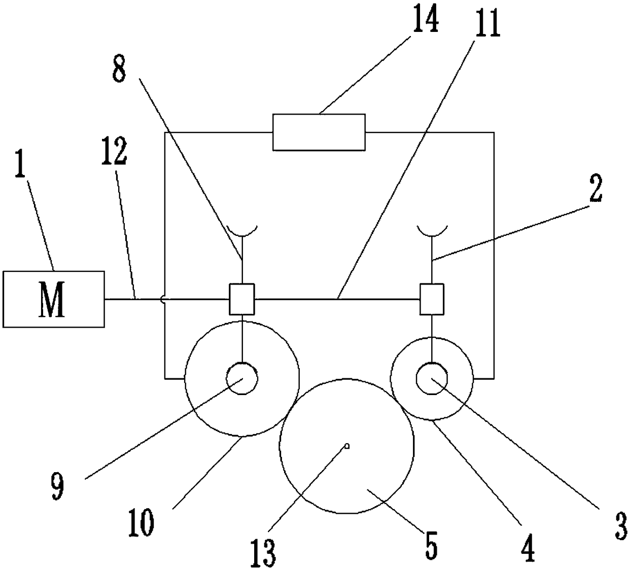
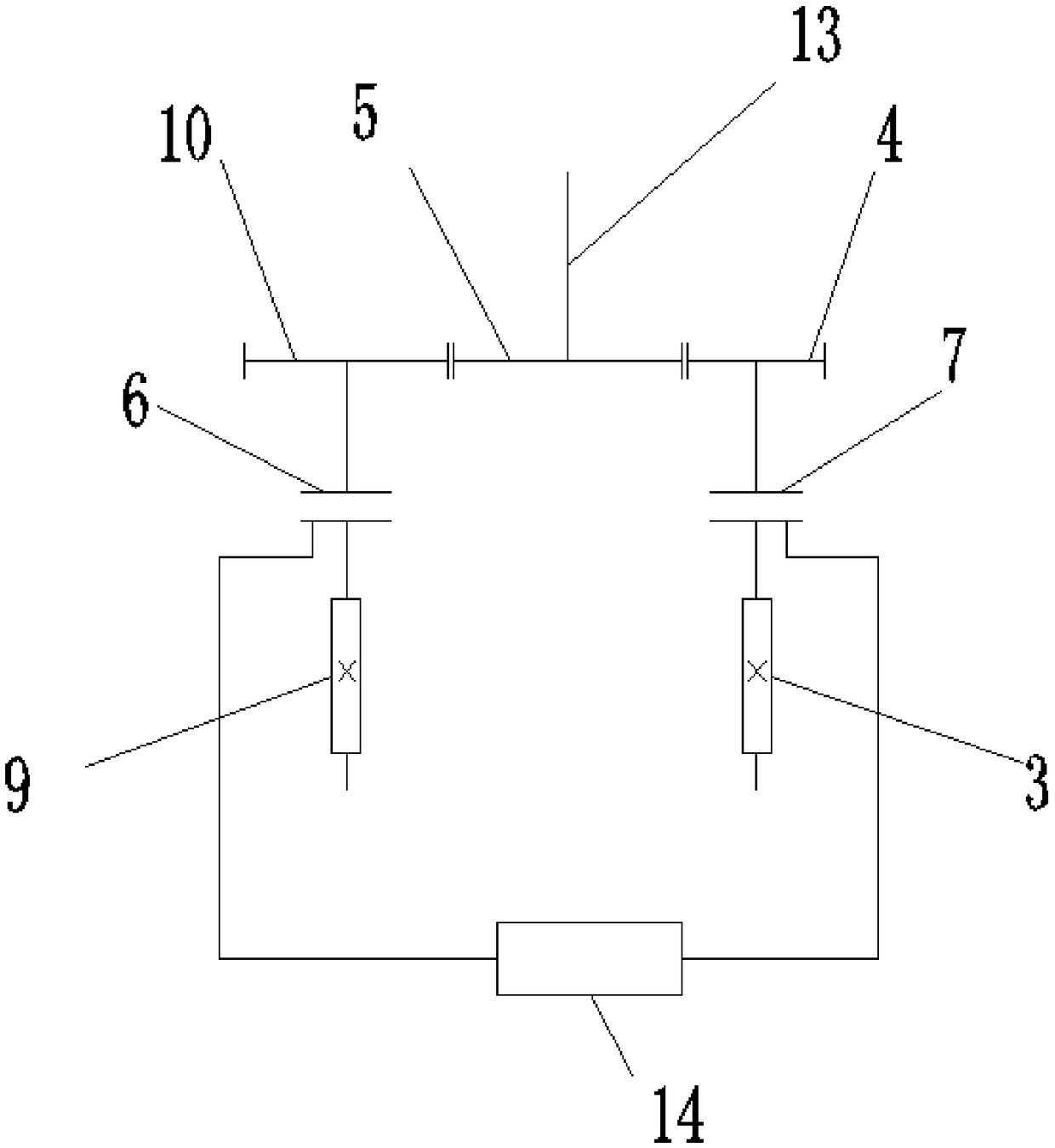
[0043] Such as Figure 1-4 As shown, the present invention provides a novel worm gear transmission, the basic technical scheme is as follows: including input shaft 12, first gear worm gear 2, second gear worm gear 8, first gear worm 3, second gear worm 9, second gear clutch 6, first gear Gear clutch 7, first gear reduction gear 4, second gear reduction gear 10, output gear 5 and output shaft 13, coaxial connection between the first gear worm gear 2 and the second gear worm gear 8, the input shaft 12 is fixedly connected On the worm shaft 11 that drives the first gear worm gear 2 or the second gear worm gear 8, the first gear worm gear 2 meshes with the first gear worm 3, and the second gear worm gear 8 meshes with the second gear worm 9 , the first gear worm 3 is coaxially connected to the axle of the first gear reduction gear 4 through the first gear clutch 7, and the second gear worm 9 is coaxially connected to the second gear reduction gear 10 through the second gear clutch...
Embodiment 2
[0052] Such as Figure 5 As shown, the present invention provides a worm gear transmission for electric vehicles, which is improved on the basis of the first embodiment to be suitable for driving devices such as the engine 21 or the one-way rotating electric motor 1 . The improvement point is that a reverse gear mechanism and a drive shaft are added, the reverse gear mechanism includes a reverse gear synchronizer 15 and a reversing gear mechanism, the gear hub of the reverse gear synchronizer 15 is fixedly connected with the drive shaft, and the reverse gear synchronizer The synchronous ring on one side of the gear hub 15 is fixedly installed on the input shaft 12, and the synchronous ring on the other side of the toothed hub is fixedly installed on the wheel shaft of the input gear 16 of the reversing gear mechanism, so The wheel shaft of the input gear 16 is a sleeve shaft vacantly sleeved on the drive shaft, and the wheel shaft of the input gear 16 is connected with the dri...
Embodiment 3
[0060] Such as Figure 6 As shown, a further improvement has been made on the basis of Embodiment 2, mainly to adapt to hybrid vehicles, which must be driven by both the motor and the engine 21 . Therefore, the improvement of this embodiment is that: a driving device conversion mechanism is also provided, including an engine switching clutch and a motor switching clutch 23, and there are two drive shafts and the input shaft 12, and the drive shaft includes an engine drive shaft And the motor drive shaft, the input shaft 12 includes the engine input shaft 12 and the motor input shaft 12 respectively connected to the two sections of the worm gear shaft 11, the engine drive shaft is connected to the reverse gear synchronizer 15 through the engine switching clutch The gear hub of the gear hub, the reverse gear synchronizer 15 is located at the synchronous ring on the side of the gear hub and the reverse gear output gear 20 is fixedly installed on the engine input shaft 12, and the m...
PUM
 Abstract
Description
Claims
Application Information
 - R&D Engineer
- R&D Manager
- IP Professional
- Industry Leading Data Capabilities
- Powerful AI technology
- Patent DNA Extraction
Browse by: Latest US Patents, China's latest patents, Technical Efficacy Thesaurus, Application Domain, Technology Topic, Popular Technical Reports.
© 2024 PatSnap. All rights reserved.Legal|Privacy policy|Modern Slavery Act Transparency Statement|Sitemap|About US| Contact US: help@patsnap.com


