
Safety protection device for automobile conveying line

A technology of safety protection device and conveyor line, which is applied in conveyors, mechanical conveyors, transportation and packaging, etc., can solve the problems of no protective measures on the conveyor line, the height of the support plate is not adjustable, and the safety hazards are large, so as to prevent personal injury. Accidents, improve the level of safety management, and ensure the effect of physical and mental safety

Inactive Publication Date: 2019-02-15
黄石佳鼎自动化科技有限公司
View PDF0 Cites 2 Cited by
  • Summary
  • Abstract
  • Description
  • Claims
  • Application Information

AI Technical Summary

Problems solved by technology

[0006] The purpose of the present invention is to provide a safety protection device used on the automobile conveying line to solve the problem that the existing automobile conveying line proposed in the above-mentioned background technology has problems when the automobile enters the conveying line through the support plate during use. The height of the support plate cannot be adjusted, and the height of the support plate must match the height of the conveying line, which limits the use of the support plate; since there are no specific and effective protective measures on the conveying line, between two car bodies or on the conveying trolley, If the operator is negligent, or other personnel who are not familiar with the position, such as inspectors and craftsmen, enter the operation area, there is a danger of being brought into the conveyor line by the conveyor trolley, which poses a serious safety hazard.

Method used


Image

  • Safety protection device for automobile conveying line
  • Safety protection device for automobile conveying line
  • Safety protection device for automobile conveying line

Examples


Embodiment Construction

[0022] The following will clearly and completely describe the technical solutions in the embodiments of the present invention with reference to the accompanying drawings in the embodiments of the present invention. Obviously, the described embodiments are only some, not all, embodiments of the present invention. Based on the embodiments of the present invention, all other embodiments obtained by persons of ordinary skill in the art without making creative efforts belong to the protection scope of the present invention.

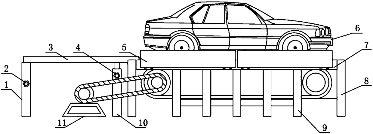
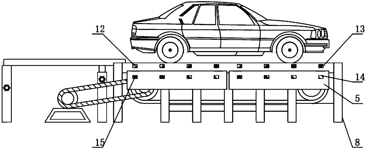
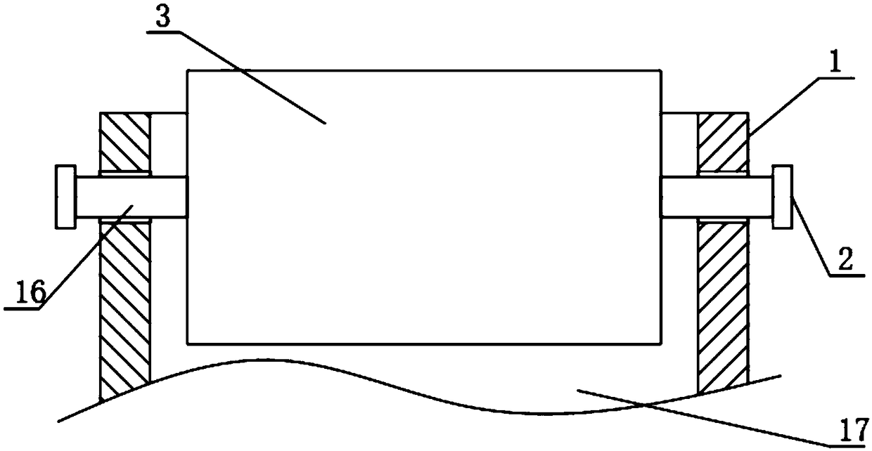
[0023] see figure 1 , figure 2 , image 3 with Figure 4 , the present invention provides a technical solution: a safety protection device for automobile conveying line, including a fixed frame 11 and a conveying mechanism, the fixed frame 11 is located on one side of the conveying mechanism, and the conveying mechanism includes two oppositely distributed support frames 8. Oppositely fixed to the support rod 7 on the inner surface of the support frame 8 an...


PUM


Abstract

The invention discloses a safety protection device for an automobile conveying line. The safety protection device comprises a fixing frame and a conveying mechanism. The fixing frame is located on oneside of the conveying mechanism. The conveying mechanism comprises two oppositely-distributed supporting frames, supporting rods oppositely fixed to the inner surfaces of the supporting frames and the conveying line located on the inner sides of the two supporting rods. In the safety protection device, a protection mechanism for protecting automobiles on the conveying line is additionally designed, protection for the automobile conveying line is improved through protection plates, the safety management level is improved, the personal hurt accident is eradiated, nature protection on operatorsis achieved, and mind and body safety of the operators is effectively guaranteed. Through the arrangement of a supporting adjusting mechanism, the relative height of a supporting plate and a fixing plate can be better adjusted according to conveying lines different in height; and a stabilization mechanism is fixed to the bottom, between the fixing frame and the conveying mechanism, of the supporting plate, so that when the automobiles pass through the supporting plate, the supporting plate is strengthened, and supporting plate damage is reduced.

Description

technical field [0001] The invention belongs to the technical field of automobile conveying lines, and in particular relates to a safety protection device used on automobile conveying lines. Background technique [0002] Only a small part of the automobile conveying lines in my country's automobile industry adopts robot automation, while most enterprises still use manual picking and placing of workpieces, and conveying trolleys to transport body bodies; with the continuous improvement of enterprises' requirements for body production efficiency, the production rhythm Accelerated, the conveying speed has been greatly improved, and the requirements for safety protection have become more prominent while fully meeting the production capacity and quality. [0003] However, the existing automobile conveyor line has the following deficiencies in the process of use: [0004] 1. When the car enters the conveyor line through the support plate, the height of the support plate cannot be ...

Claims


Application Information

Patent Timeline
Patent Type & Authority Applications(China)
IPC IPC(8): B65G35/00
CPCB65G35/00
Inventor 汪建家
Owner 黄石佳鼎自动化科技有限公司
Learn More