Multifunctional seat for medical care
A multifunctional seat technology, applied in the field of medical care, can solve the problems of single structure and single function of the medical seat, and achieve the effect of improving comfort, preventing movement and good stability
- Summary
- Abstract
- Description
- Claims
- Application Information
AI Technical Summary
Problems solved by technology
Method used
Image
Examples
specific Embodiment approach 1
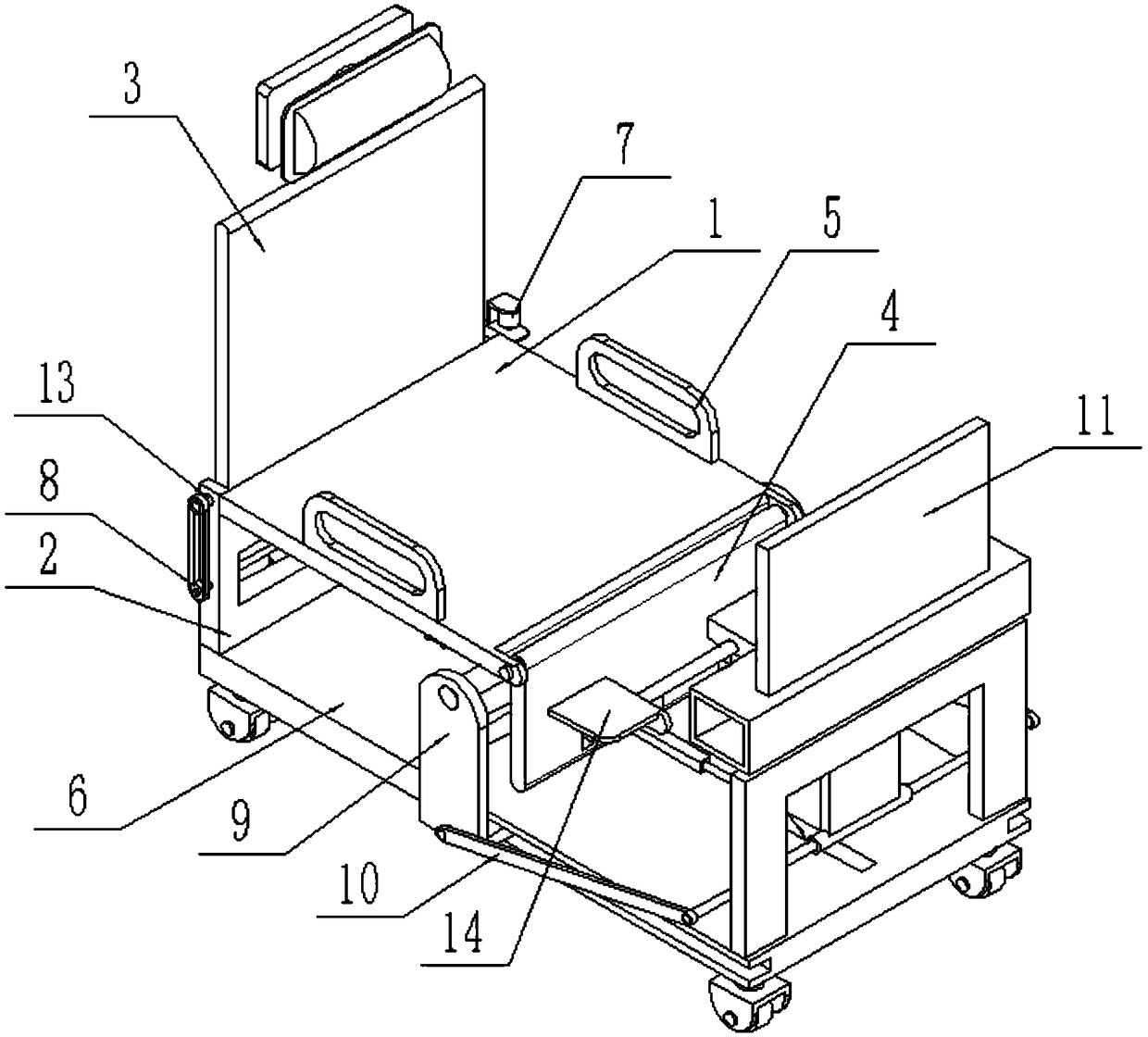
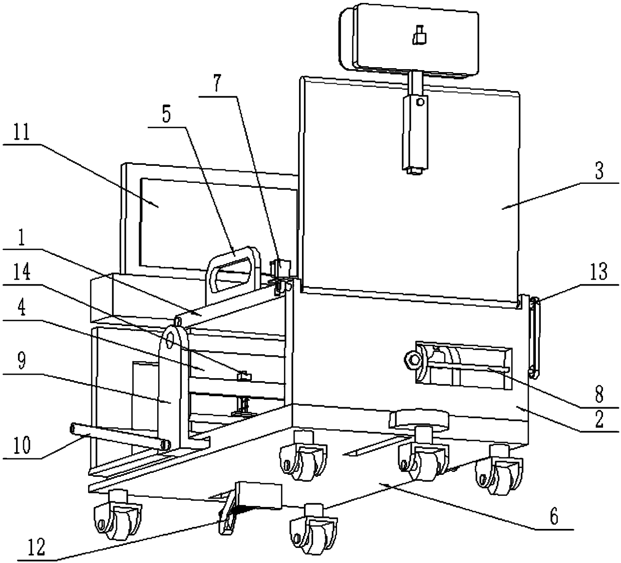
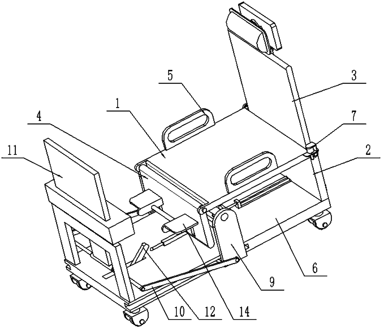
[0043] Such as Figure 1-17 As shown, a multifunctional chair for medical care, including a seat 1, a vertical support 2, a backrest assembly 3, a leg support 4, an armrest 5, a movable base 6, a backrest angle adjustment mechanism 7, and a linkage wheel assembly 8. The supporting plate angle adjustment mechanism 9, the push rod assembly 10, the lifting display mounting frame 11 and the base positioning mechanism 12, the rear end of the seat 1 is fixedly connected to the vertical support plate 2; the vertical support plate 2 The lower end is fixedly connected to the rear end of the movable base 6; the lower end of the backrest assembly 3 is rotatably connected to the upper end of the vertical support plate 2 through the backrest rotating shaft 13; the front end; the left and right ends of the top surface of the seat 1 are fixedly connected with an armrest 5;
[0044] The backrest angle adjustment mechanism 7 includes a servo motor 7-1, a motor base 7-2, a worm screw 7-3, a ro...
specific Embodiment approach 2
[0045] Such as Figure 1-17 As shown, the backrest assembly 3 includes a backrest body 3-1, a rectangular sliding sleeve 3-2, a positioning bolt 3-3, a rectangular sliding rod 3-4, a fixed seat plate 3-5, a rectangular spring rod 3-6, a compression Spring 3-7, insertion rod 3-8 and head resting plate 3-9; The lower end of said backrest body 3-1 is fixedly connected on the backrest rotating shaft 13; The upper end of said backrest body 3-1 rear side is fixedly connected to a rectangular The sliding sleeve 3-2 and the rectangular sliding rod 3-4 are slidably connected in the rectangular sliding sleeve 3-2; the rectangular sliding sleeve 3-2 is threaded to connect the positioning bolt 3-3, and the inner top of the positioning bolt 3-3 On the rectangular sliding sleeve 3-2; the top of the rectangular sliding rod 3-4 is fixedly connected to the fixed seat plate 3-5; the front end of the rectangular spring rod 3-6 is fixedly connected to the head backing plate 3-9; Rectangular spri...
specific Embodiment approach 3
[0047] Such as Figure 1-17 As shown, the linkage wheel assembly 8 includes a first pulley 8-1, a second pulley 8-2, a belt 8-3, a linkage shaft 8-4 and a driving bevel gear 8-5; the first pulley 8-1 is fixedly connected to the right end of the backrest rotating shaft 13, the first pulley 8-1 is connected to the second pulley 8-2 through the transmission of the belt 8-3, and the second pulley 8-2 is fixedly connected to the joint shaft 8-4. At the right end, the linkage shaft 8-4 is rotatably connected to the vertical support plate 2 through a bearing with a seat, and the left end of the linkage shaft 8-4 is fixedly connected to the driving bevel gear 8-5, and the driving bevel gear 8-5 is meshed with the transmission connection bracket angle adjustment mechanism 9.
[0048]When the linkage wheel assembly 8 is in use, the backrest shaft 13 can drive the linkage wheel assembly 8 to work when the backrest shaft 13 rotates; When rotating clockwise, the first pulley 8-1 can be d...
PUM
 Abstract
Description
Claims
Application Information
 - R&D Engineer
- R&D Manager
- IP Professional
- Industry Leading Data Capabilities
- Powerful AI technology
- Patent DNA Extraction
Browse by: Latest US Patents, China's latest patents, Technical Efficacy Thesaurus, Application Domain, Technology Topic, Popular Technical Reports.
© 2024 PatSnap. All rights reserved.Legal|Privacy policy|Modern Slavery Act Transparency Statement|Sitemap|About US| Contact US: help@patsnap.com


