
Metal bar displacement speed sensor and manufacturing method of metal bar

A technology of a speed sensor and a manufacturing method, applied in the field of sensors, can solve the problems of difficult manufacturing and installation, expensive encoders, and high failure rate of potentiometers, and achieve the effects of reducing supporting facilities, reducing costs, and saving space

Inactive Publication Date: 2019-02-12
邹明高
View PDF5 Cites 0 Cited by
  • Summary
  • Abstract
  • Description
  • Claims
  • Application Information

AI Technical Summary

Problems solved by technology

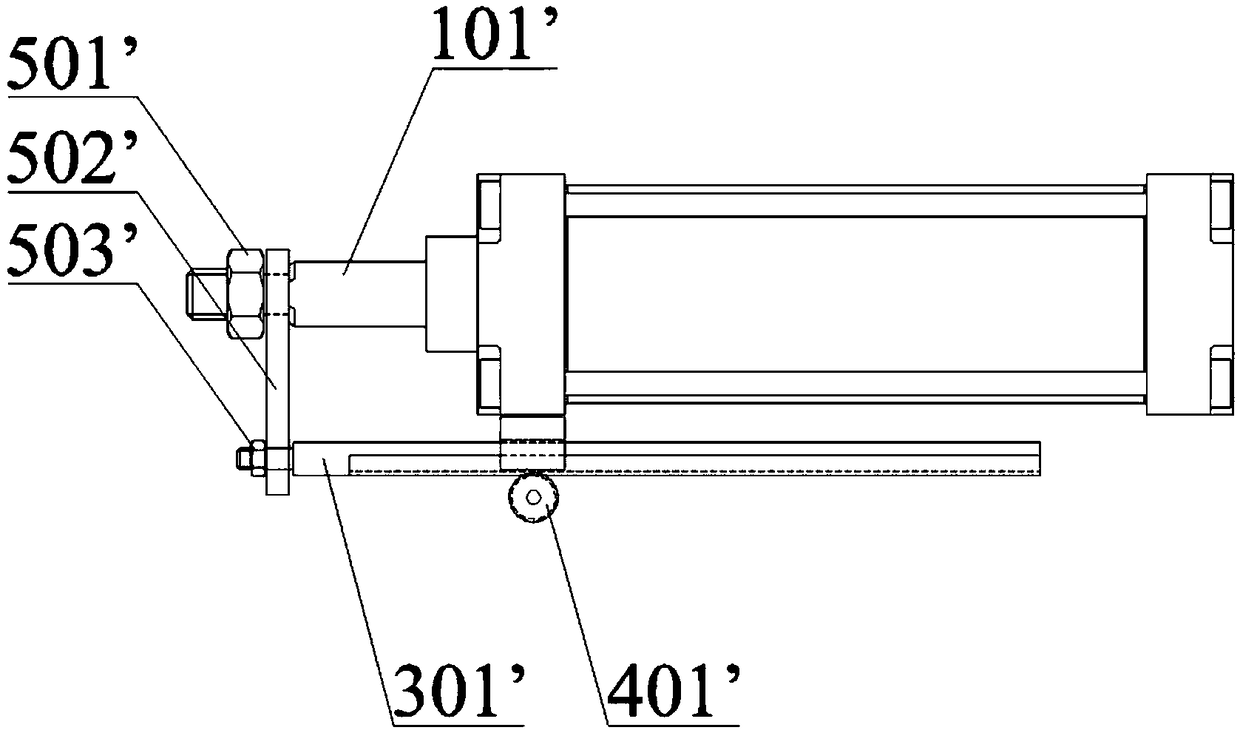
[0003] Although the existing detection method can complete the detection of the displacement and speed of the metal rod 101', if the metal rod 101' is surrounded by other utensils and equipment, this method will not be applicable
In addition, if the length of the metal rod 101' is longer, the length and volume of its supporting facilities will increase accordingly, making it difficult to manufacture and install, and the measurement accuracy cannot be guaranteed.
If a rotary encoder is used, the encoder is more expensive
If a potentiometer is used, although the price is cheap, its use is affected by environmental factors. Once oil mist and dust enter the magnetic strip, the potentiometer has a high failure rate and cannot be used.

Method used


Image

  • Metal bar displacement speed sensor and manufacturing method of metal bar
  • Metal bar displacement speed sensor and manufacturing method of metal bar
  • Metal bar displacement speed sensor and manufacturing method of metal bar

Examples


Embodiment Construction

[0033] The technical solutions of the present application will be clearly and completely described below in conjunction with the accompanying drawings. Apparently, the described embodiments are some of the embodiments of the present application, not all of them. Based on the embodiments in this application, all other embodiments obtained by persons of ordinary skill in the art without making creative efforts belong to the scope of protection of this application.

[0034] In the description of this application, it should be noted that the terms "center", "upper", "lower", "left", "right", "vertical", "horizontal", "inner", "outer" etc. The indicated orientation or positional relationship is based on the orientation or positional relationship shown in the drawings, and is only for the convenience of describing the present application and simplifying the description, rather than indicating or implying that the referred device or element must have a specific orientation, use a spec...


PUM


Abstract

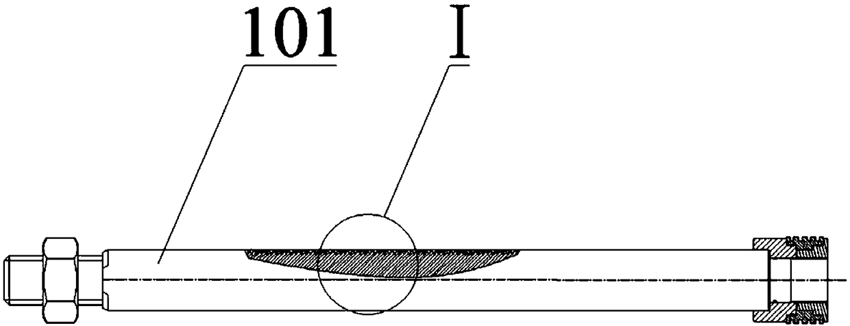
The invention relates to the technical field of sensors, in particular to a metal bar displacement speed sensor and a manufacturing method of a metal bar. The metal bar displacement speed sensor comprises a metal bar and a sensor, wherein mounting grooves are formed in the metal bar, and the mounting grooves are arranged in an equally-spaced manner in the length direction of the metal bar; each mounting groove is internally provided with a non-magnetic material; and the sensor is used for measuring the change of magnetic induction intensity for the linear motion of the metal bar. The manufacturing method of the metal bar comprises the following steps: forming a plurality of equally-spaced grooves in the metal bar; and enabling the grooves to be filled with the non-magnetic material. According to the metal bar displacement speed sensor and the manufacturing method of the metal bar provided by the invention, the equally-spaced mounting grooves are formed in the length direction of the metal bar, the mounting grooves are filled with the non-magnetic material, and the sensor is used for measuring the change of magnetic induction intensity for the linear motion of the metal bar, so thatthe supporting facilities are reduced, the space is saved, and the cost is reduced.

Description

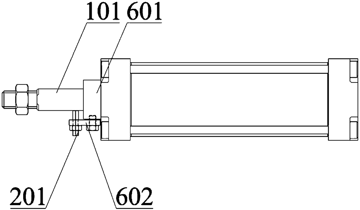
technical field [0001] The present application relates to the technical field of sensors, in particular to a metal rod displacement velocity sensor and a manufacturing method of the metal rod. Background technique [0002] The existing technology for detecting the displacement and speed of metal rods is generally to add a set of supporting devices on one side of the metal rod, such as figure 1 As shown, the metal rod 101' and the long straight rack 301' are fixed on the connecting plate 502' with the first nut 501' and the second nut 503', and then the circular gear 401' is driven by the long straight rack 301', The linear motion of the metal rod 101' is transformed into the circular motion of the circular gear 401', and then the circular gear 401' drives the rotary encoder or potentiometer to complete the detection of the linear displacement and speed of the metal rod 101'. [0003] Although the existing detection method can complete the detection of the metal rod 101' dis...

Claims


Application Information

Patent Timeline
Patent Type & Authority Applications(China)
IPC IPC(8): G01D21/02
CPCG01D21/02
Inventor 邹明高
Owner 邹明高
Learn More