


Quick Research
Generate reliable direction feasibility study reports for your R&D in just a few steps.

Technical Q&A
Discover and master advanced knowledge NOW. Basics, ideas, possibilities, all at once.

Find Solutions
As an expert in R&D theories, this can generate solutions to your technical problems instantly.

Evaluate Feasibility
Analyze your overall solution with one click, know your potential R&D risks in advance.

Monitor Landscape
Get weekly tech updates, stay abreast of the latest tech innovations and key insights.
Air conditioner and control method and device thereof
A control method and a technology of a control device, which are applied in the direction of control input involving air characteristics, control input involving environmental factors, space heating and ventilation control input, etc., which can solve problems such as insufficient response and inaccurate control, and achieve comfortable Control, control timely and accurately, and ensure the effect of accuracy
- Summary
- Abstract
- Description
- Claims
- Application Information
AI Technical Summary
Problems solved by technology
Method used
Image

Examples
Embodiment 1
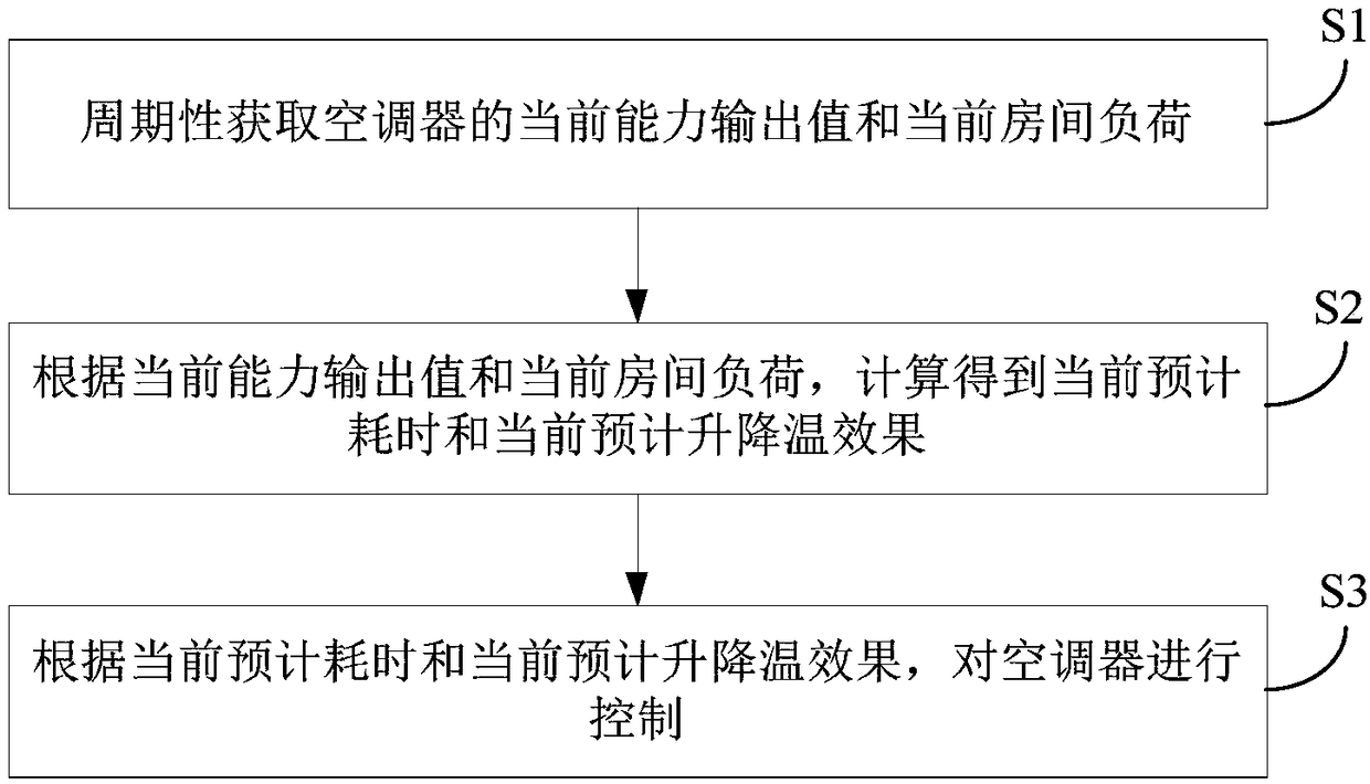
[0030] figure 1 It is a flow chart of the control method of the air conditioner in Embodiment 1 of the present application.
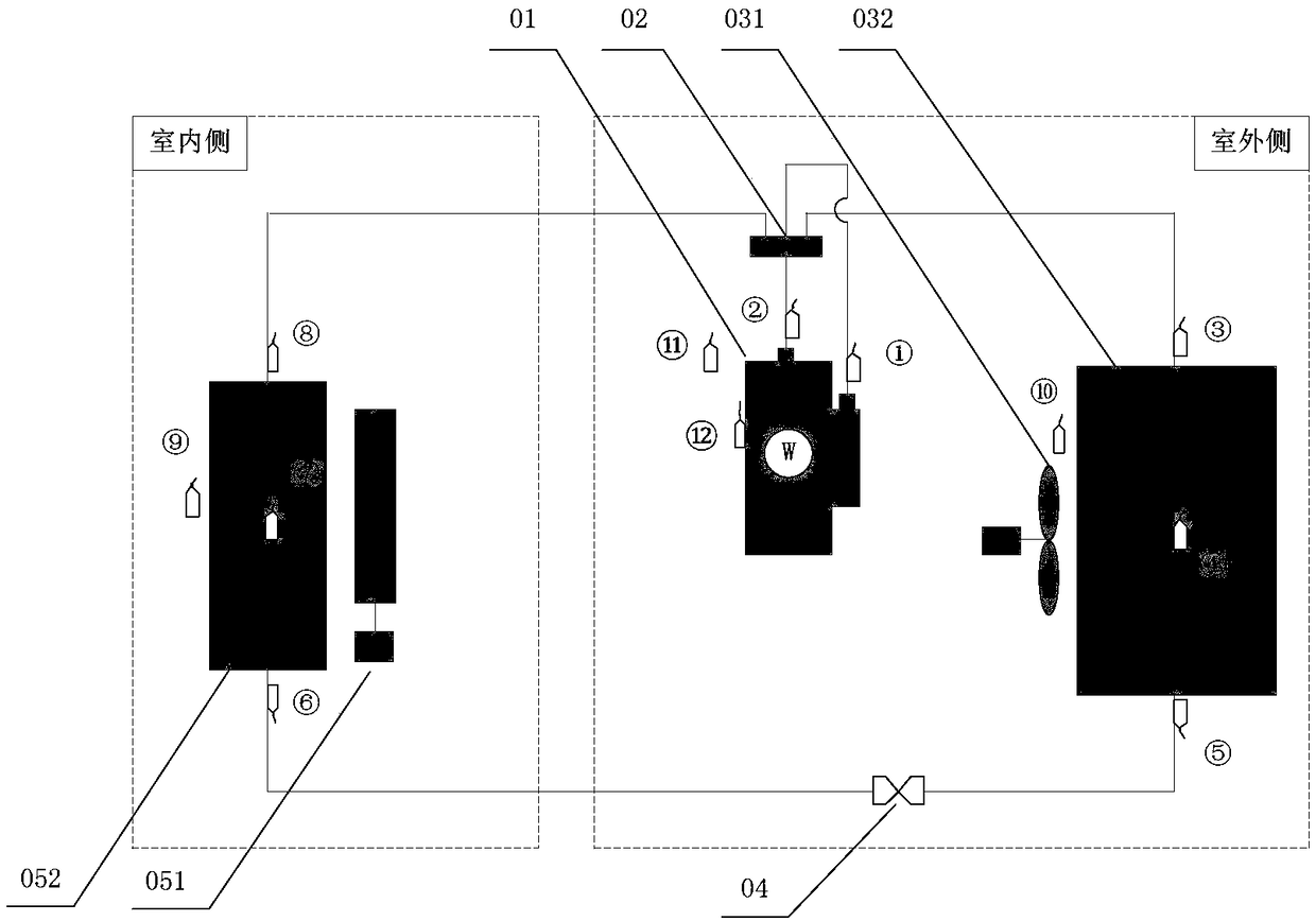
[0031] In the examples of this application, as figure 2 As shown, the air conditioner may include an outdoor side and an indoor side. Wherein, the outdoor side includes a compressor 01 , a four-way valve 02 , an outdoor fan 031 , an outdoor heat exchanger 032 and a throttling component 04 , and the indoor side includes an indoor fan 051 and an indoor heat exchanger 052 . The exhaust port of the compressor 01 is connected to the first end of the four-way valve 02, the second end of the four-way valve 02 is connected to one end of the indoor heat exchanger 052, and the other end of the indoor heat exchanger 052 is connected to the throttle member 04. One end is connected, the other end of the throttling part 04 is connected to one end of the outdoor heat exchanger 032, the other end of the outdoor heat exchanger 032 is connected to the fourth end of th...
Embodiment 2
[0115] Figure 5 It is a schematic block diagram of the control device of the air conditioner in Embodiment 2 of the present application. Such as Figure 5 As shown, the air conditioner control device 100 in the embodiment of the present application includes: an acquisition module 110 , a calculation module 120 and a control module 130 .
[0116] Wherein, the acquisition module 110 is used to periodically acquire the current capacity output value and the current room load of the air conditioner, and the calculation module 120 is used to calculate the current estimated time-consuming and the current expected cooling effect according to the current capacity output value and the current room load, and control The module 130 is used to control the air conditioner according to the current estimated time-consuming and the current estimated cooling effect.
[0117] According to an embodiment of the present application, the acquisition module 110 is configured to: periodically acqui...
PUM
 Abstract
Description
Claims
Application Information
 - R&D Engineer
- R&D Manager
- IP Professional
- Industry Leading Data Capabilities
- Powerful AI technology
- Patent DNA Extraction
Browse by: Latest US Patents, China's latest patents, Technical Efficacy Thesaurus, Application Domain, Technology Topic, Popular Technical Reports.
© 2024 PatSnap. All rights reserved.Legal|Privacy policy|Modern Slavery Act Transparency Statement|Sitemap|About US| Contact US: help@patsnap.com