
Engine annular combustion chamber in high-mach-number flight and spiral inclined knocking combustion method

An annular combustion chamber, high Mach number technology, used in ramjet engines, mechanical equipment, etc., can solve the problems of insufficient fuel and air mixing, weakened engine performance, oblique detonation, stationary instability, etc., and achieves Mach reflection. The effect of suppressing, reducing relative resistance, and preventing flow congestion

Active Publication Date: 2019-02-12
中国空气动力研究与发展中心吸气式高超声速技术研究中心
View PDF6 Cites 7 Cited by
  • Summary
  • Abstract
  • Description
  • Claims
  • Application Information

AI Technical Summary

Problems solved by technology

[0004] (1) Combustion scheme based on oblique detonation premixing produces the mixing problem of fuel and air at high Mach number: at high Mach number, the penetration depth of the fuel jet and the growth rate of the mixed layer are greatly suppressed, resulting in Inadequate mixing of fuel and air
[0005] (2) Controllability of oblique detonation
At present, preliminary experiments and numerical studies have shown that the reason for the poor stationary stability of oblique detonation in the combustion chamber is that oblique detonation produces Mach reflection in the confined space and causes flow blockage, which in turn leads to oblique detonation instability. and propagate upstream
And it is more difficult to control if the oblique detonation is produced by multiple reflections of the shock wave
[0006] (3) The shock wave generating device brings resistance to the aircraft: the shock wave generating device generates sufficient shock waves to induce oblique detonation, and the shock wave generating device needs to have sufficient windward area to achieve oblique detonation detonation , which leads to a relatively large frontal area of ​​the shock wave generating device relative to the cross-sectional area of ​​the flow channel in the existing configuration, that is, a relatively large blockage, which brings additional large resistance while generating shock waves and weakens the engine's performance. performance

Method used


Image

  • Engine annular combustion chamber in high-mach-number flight and spiral inclined knocking combustion method
  • Engine annular combustion chamber in high-mach-number flight and spiral inclined knocking combustion method
  • Engine annular combustion chamber in high-mach-number flight and spiral inclined knocking combustion method

Examples


Embodiment Construction

[0026] The following describes the implementation of the present invention through specific specific examples, and those skilled in the art can easily understand other advantages and effects of the present invention from the content disclosed in this specification. The present invention can also be implemented or applied through other different specific embodiments, and various details in this specification can also be modified or changed based on different viewpoints and applications without departing from the spirit of the present invention.

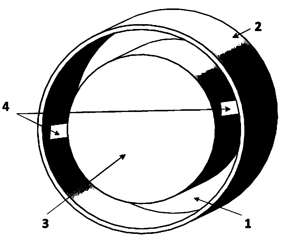
[0027] A high Mach number in-flight engine annular combustion chamber, comprising: an inner column 3, a shell 2 and a shock wave generator 4. The shell 2 surrounds the outer side of the inner column 3 at a certain interval, and the inner wall of the shell 2 and the outer wall of the inner column 3 An annular combustion chamber 1 is formed in between. The annular gap between the inner wall of the outer shell and the outer wall of the inner ...


PUM


Abstract

The invention provides an engine annular combustion chamber in high-mach-number flight and a spiral inclined knocking combustion method. The engine annular combustion chamber comprises an inner cylinder, an outer shell and a shock wave generation device; the outer shell is encircled on the outer side of the inner cylinder; an annular combustion chamber is formed between the inner wall of the outershell and the outer wall of the inner cylinder; supersonic combustible gas flows in the axial direction of the annular combustion chamber; the shock wave generation device is positioned in the annular combustion chamber, and the placing direction thereof is towards the gas current flowing direction; the supersonic combustible gas currents pass through the shock wave generation device as an obstacle to generate shock waves; the shock waves ignite the combustible gas and induce to generate inclined knocking waves; and the inclined knocking waves are spirally developed in the annular combustionchamber to finally ignite the combustible gas in the whole annular combustion chamber. The engine annular combustion chamber can prominently improve the fuel mixing under the condition of high mach number, inhibits the mach reflection of the inclined knocking, reduces the total pressure loss caused by the inclined knocking combustion, improves the inclined knocking controllability, and reduces relative resistance of the shock wave generation device.

Description

Technical field [0001] The invention belongs to the technical field of air-breathing hypersonic aircraft, in particular to an annular combustion chamber of an engine in flight at a high Mach number and a method for using the combustion chamber to perform spiral oblique detonation combustion. Background technique [0002] Scramjet is currently the main power generation scheme for air-breathing hypersonic aircraft, and is suitable for flight conditions with a flying Mach number greater than 4. In high-speed airflow, fuel mixing and flame stabilization are relatively difficult, and the situation is more severe at high Mach numbers. Therefore, traditional scramjet engines have adopted support rods, support plates, ramp injection, cavity and other hybrid enhancement and flame stabilization devices. Although these devices can achieve good results within a certain range of operating conditions, under high Mach number flight conditions (Ma≥6), these devices have limited performance comp...

Claims


Application Information

Patent Timeline
Patent Type & Authority Applications(China)
IPC IPC(8): F02K7/10
CPCF02K7/10
Inventor 刘彧肖保国王兰晏至辉郑忠华杨顺华邢建文蒋劲张顺平王超李季郑榆山向周正蔡建华郑帅罗佳茂
Owner 中国空气动力研究与发展中心吸气式高超声速技术研究中心
Learn More