
Simple automatic lifting escape device for top platform

An automatic lifting and escape device technology, applied in the field of escape platforms, can solve problems such as broken ropes, increased demand, troublesome equipment operation, etc., and achieve the effects of stable descent and rise, huge economic benefits, and avoiding left and right swings

Inactive Publication Date: 2019-02-12
叶泓希
View PDF7 Cites 1 Cited by
  • Summary
  • Abstract
  • Description
  • Claims
  • Application Information

AI Technical Summary

Problems solved by technology

[0002] Escape equipment is the equipment that can leave the dangerous area as quickly as possible when people encounter some unexpected situations, so as to ensure the safety of people's lives. With the development of society, various escape equipment appear in our lives , the emergence of escape equipment has reduced casualties to a certain extent. However, some casualties cannot be avoided when some fire accidents occur, because some escape equipment is very inconvenient and unstable to use. Therefore, for The demand for a simple automatic lifting escape device for the top floor platform is increasing day by day
[0003] Some escape devices currently on the market are particularly unstable when there is wind during use, which also poses a threat to the safety of users to a certain extent, because improper operation may affect the safety of escape during the escape process. There are also some equipment that are particularly troublesome to operate and are not suitable for most people. Some escape equipment cannot reduce the speed well when the descending speed is too fast, because too many people may descend too fast. The danger of rope breakage occurs, therefore, a simple automatic lifting escape device for the top floor platform is proposed in view of the above problems

Method used


Image

  • Simple automatic lifting escape device for top platform
  • Simple automatic lifting escape device for top platform
  • Simple automatic lifting escape device for top platform

Examples


Embodiment Construction

[0019] The following will clearly and completely describe the technical solutions in the embodiments of the present invention with reference to the accompanying drawings in the embodiments of the present invention. Obviously, the described embodiments are only some, not all, embodiments of the present invention. Based on the embodiments of the present invention, all other embodiments obtained by persons of ordinary skill in the art without making creative efforts belong to the protection scope of the present invention.

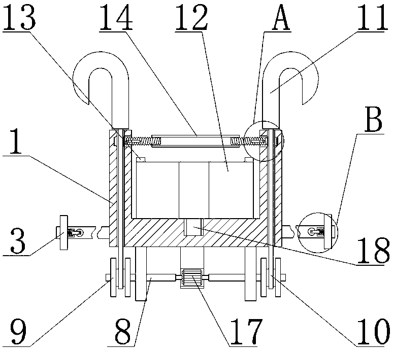
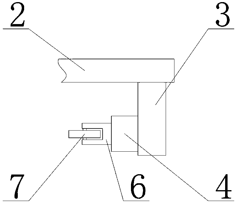
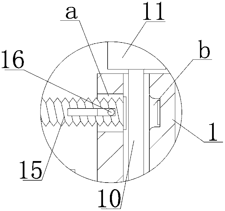
[0020] see Figure 1-4 , the present invention provides a technical solution:

[0021] A simple automatic lifting escape device for a top floor platform, comprising a fixed frame 1, a fixed rod 2 is fixedly connected to the outside of the fixed frame 1, a baffle plate 3 is fixedly connected to the front end of the fixed rod 2, and a front end surface of the fixed rod 2 is provided There is a sleeve rod 4, and the sleeve rod 4 is fixedly connected with the baf...


PUM


Abstract

The invention relates to the technical field of escape platforms, in particular to a simple automatic lifting escape device for a top platform. The device comprises a fixed rack. A fixed bar is fixedly connected to the outer side of the fixed rack, the front end surface of the fixed bar is fixedly connected to a baffle plate, a loop bar is arranged on the front end surface of the fixed bar, the loop bar is fixedly connected to the baffle plate, a spring is connected to the inner side of the loop bar, a supporting rod is connected to the inner side of the loop bar in a sleeving manner, the other end of the spring is fixedly connected to a supporting rod, the other end of the supporting rod is rotatably connected to a roller through a rotary shaft, and a sliding shaft is rotatably connectedto the bottom end surface of the fixed rack through a supporting plate. According to the device, by arranging the baffle plate, the spring and the roller, the stable lifting process is guaranteed by limitation of the baffle plate, the phenomenon of swinging left and right is avoided to the maximum extent, the descending friction force is reduced to the maximum extent by means of the spring and theroller, the phenomenon of stagnation is avoided, and the simple automatic lifting escape device descends and ascends more stably.

Description

technical field [0001] The invention relates to the technical field of escape platforms, in particular to a simple automatic lifting escape device for a top platform. Background technique [0002] Escape equipment is the equipment that can leave the dangerous area as quickly as possible when people encounter some unexpected situations, so as to ensure the safety of people's lives. With the development of society, various escape equipment appear in our lives , the emergence of escape equipment has reduced casualties to a certain extent. However, some casualties cannot be avoided when some fire accidents occur, because some escape equipment is very inconvenient and unstable to use. Therefore, for The demand for a simple automatic lifting escape device for a top floor platform is increasing day by day. [0003] Some escape devices currently on the market are particularly unstable when there is wind during use, which also poses a threat to the safety of users to a certain exten...

Claims


Application Information

Patent Timeline
IPC IPC(8): A62B1/10A62B1/18
CPCA62B1/10A62B1/18
Inventor 叶泓希林栩如叶泓辰
Owner 叶泓希
Learn More