
Bearing stop pin shaft

A stop pin and stop technology, applied in the direction of pivot connection, etc., can solve the problems of structural weight and local stress corrosion of space thread parts, and achieve the effect of avoiding local structural corrosion and fatigue, reducing structural weight and saving structural space.

Inactive Publication Date: 2019-02-05
XIAN AIRCRAFT DESIGN INST OF AVIATION IND OF CHINA
View PDF0 Cites 0 Cited by
  • Summary
  • Abstract
  • Description
  • Claims
  • Application Information

AI Technical Summary

Problems solved by technology

[0003] Conventional stop connection structures with high load-bearing capacity are mainly designed with large connecting pins and stop bolts or stop pins. This design mode has certain disadvantages in terms of structural weight, space and local stress corrosion of threaded parts.

Method used


Image

  • Bearing stop pin shaft
  • Bearing stop pin shaft
  • Bearing stop pin shaft

Examples


specific Embodiment

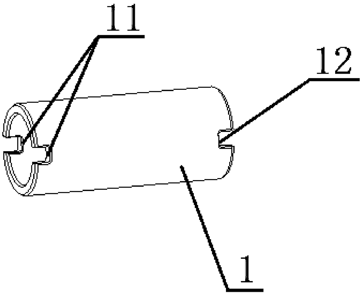
[0030] The bearing stop pin provided by the present invention is as figure 1 As shown, it is used for bearing and hinge between the first connecting piece 8 and the second connecting piece 9, the stopper pin includes a hollow pin 1, a stopper, a first retaining ring 2, a second retaining ring 3 and Transmission Parts.

[0031] The hollow pin shaft 1 runs through the first connecting piece 8 and the second connecting piece 9, the outer wall of the hollow pin shaft 1 is in contact with the first connecting piece 8 and the second connecting piece 9 respectively, and the first connecting piece is carried by the hollow pin shaft 1 Part 8 and the load of the second connecting part 9, such as figure 2 As shown, a groove A11 is formed on one end surface of the hollow pin shaft 1, and a groove B12 is formed on the other end surface of the hollow pin shaft 1. In this embodiment, the groove A11 is symmetrically arranged on both radial sides of the hollow pin shaft 1. , The groove B12 ...


PUM


Abstract

The invention relates to the technical field of pin shaft structure design, and particularly provides a bearing stop pin shaft for bearing and hinging between a first connecting piece and a second connecting piece. A hollow pin shaft body, a stop piece, a first check ring, a second check ring and a transmission piece are included. The hollow pin shaft body penetrates through the first connecting piece and the second connecting piece. A groove A is formed in one end face of the hollow pin shaft body, and a groove B is formed in the other end face of the hollow pin shaft body. The stop piece sleeves one side of the hollow pin shaft body and coaxially rotates with the hollow pin shaft body. An inner ring of the stop piece is provided with a protruding block A matched with the groove A. A stopboss is arranged on the first connecting piece and drives the stop piece and the first connecting piece to coaxially rotate. The first check ring is fixed to one side of the stop piece, the second check ring is fixed to the other side of the hollow pin shaft body, and the end face of the second check ring is provided with a protruding block B matched with the groove B. The transmission piece penetrates through the hollow pin shaft body, one end of the transmission piece is fixed to the first check ring and coaxially rotates with the first check ring, and the other end of the transmission piece is fixed to the second check ring and coaxially rotates with the second check ring.

Description

technical field [0001] The invention relates to the technical field of pin shaft structure design, in particular to a load-bearing stop pin shaft. Background technique [0002] In aerospace structures, there are many connection parts with large loads and the structural space is tight. A structural design with complete stop function and low weight is required. At the same time, design factors such as reliability, safety, corrosion, and fatigue need to be considered comprehensively. [0003] Conventional stop connection structures with high load-bearing capacity are mainly designed with large connecting pins and stop bolts or stop pins. This design mode has certain disadvantages in terms of structural weight, space and local stress corrosion of threaded parts. Contents of the invention [0004] In order to overcome at least one defect in the above-mentioned prior art, the present invention provides a load-bearing stop pin for carrying and hinged between the first connecting ...

Claims


Application Information

Patent Timeline
Patent Type & Authority Applications(China)
IPC IPC(8): F16C11/04F16C11/10
CPCF16C11/04F16C11/10
Inventor 张雷杨艳马成
Owner XIAN AIRCRAFT DESIGN INST OF AVIATION IND OF CHINA
Learn More