
Reversing valve

A reversing valve and axial technology, which is applied in the field of reversing valves, can solve the problems that parts are vulnerable to impact damage, etc., and achieve the effects of convenient assembly process, alleviating liquid impact force, and convenient adjustment

Inactive Publication Date: 2019-02-05
HENAN AEROSPACE HYDRAULIC & PNEUMATIC TECH
View PDF11 Cites 2 Cited by
  • Summary
  • Abstract
  • Description
  • Claims
  • Application Information

AI Technical Summary

Problems solved by technology

[0004] The purpose of the present invention is to provide a reversing valve to solve the problem in the prior art that the flow in the outlet channel of the reversing valve suddenly increases when the reversing valve is reversing, which causes the components in the matching hydraulic system to be easily damaged by impact question

Method used


Image

  • Reversing valve
  • Reversing valve

Examples


Embodiment Construction

[0020] Embodiments of the present invention will be further described below in conjunction with the accompanying drawings.

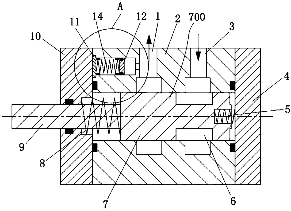
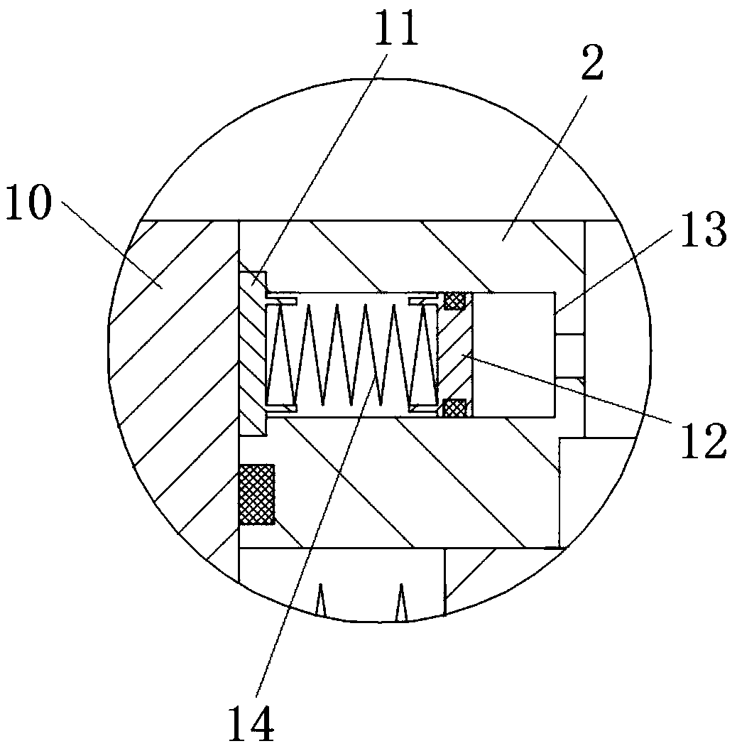
[0021] The specific embodiment of reversing valve of the present invention, as Figure 1 to Figure 2 As shown, the reversing valve in this embodiment is a two-position two-way solenoid valve.

[0022] The reversing valve includes a valve body 2, the center of the valve body 2 is provided with a through axial center hole, and the axial center hole is equipped with a valve core 700 moving along the left and right directions, and the left and right ends of the valve body 2 are respectively packaged with end caps. 10 and the bottom plate 4, the specific assembly method is bolt connection (of course, in other embodiments, other methods can be used for connection, such as press-fitting, etc.), in order to ensure the connection between the end cover 10 and the valve body 2, the bottom plate 4 and the valve body 2 are sealed and assembled to prevent oil from se...


PUM


Abstract

The invention relates to a reversing valve. The reversing valve comprises a valve body assembly, wherein an axial central hole which leftwards and rightwards extends and a valve element which is assembled into the axial center hole in a leftward and rightward guiding moving manner are arranged in the valve body assembly; a valve element passing port through which the valve element passes is formedin the left end surface, of the axial center hole, on the valve body assembly; a liquid inlet channel and a liquid outlet channel which are connected to the axial central hole and radially extend arearranged in the valve body assembly; the valve element is glidingly assembled in the axial central hole in order to control the liquid inlet channel and the liquid outlet channel to be connected anddisconnected; the liquid outlet channel and the liquid inlet channel are sequentially arranged at an interval from left to right; an axial communication hole which communicates with the liquid outletchannel is formed in the left end surface of the valve body assembly; a piston is glidingly assembled in the axial communication hole in a sealing manner; the reversing valve body further comprises avalve cap which is fixedly arranged on the left end surface of the valve body assembly in a splicing manner, and the valve element is prevented from falling off from the left through the valve cap; ab locking part for blocking the axial communication hole from the left side is arranged on the valve cover; an elastic part is arranged between the blocking part and the piston in a press fitting manner; and / or the blocking part, the piston and the valve body assembly encircle a sealed air chamber.

Description

technical field [0001] The invention relates to a reversing valve. Background technique [0002] In traditional hydraulic systems, reversing valves (such as two-position two-way solenoid valves, etc.) that control and change the direction of liquid flow in the hydraulic system are relatively common valves. The channel and the liquid outlet channel are provided with a valve core in the valve body, and the change of the relative position between the valve core and the valve body is used to control the on-off between the liquid inlet channel and the liquid outlet channel to meet the requirements of the system for the direction of liquid flow. Usually, the liquid inlet channel is connected with the oil pump, and the liquid outlet channel is connected with the subsequent matched hydraulic system. [0003] At the moment when the reversing valve is reversing, the flow in the outlet channel suddenly increases, resulting in a pressure peak, which causes a pressure shock to the subse...

Claims


Application Information

Patent Timeline
Patent Type & Authority Applications(China)
IPC IPC(8): F15B13/02F16K3/26F16K3/314F16K47/02F16K27/04F16K27/08
CPCF15B13/02F16K3/26F16K3/314F16K27/041F16K27/08F16K47/02
Inventor 郑芳任威张亚娟陈志鹏陈浩周洪学赵文亮国宁
Owner HENAN AEROSPACE HYDRAULIC & PNEUMATIC TECH
Learn More