
Quantification method for lithium deposition in lithium ion battery anode

A lithium-ion battery and quantification method technology, which is applied in the quantification field of lithium-ion battery negative electrode analysis, can solve the problems of reducing battery safety, fire, affecting battery capacity, etc., and achieves simple and easy test methods, accurate and reliable test results, The effect of good practicality and feasibility

Active Publication Date: 2019-02-01
HEFEI GUOXUAN HIGH TECH POWER ENERGY
View PDF10 Cites 10 Cited by
  • Summary
  • Abstract
  • Description
  • Claims
  • Application Information

AI Technical Summary

Problems solved by technology

However, there are still many properties of lithium-ion that cannot meet the needs of the public. One of them is the low-temperature charging performance. At low temperatures (below 0°C), lithium-ion power batteries will deposit lithium ions on the negative electrode of the battery during charging to form lithium metal. Not only affects the battery capacity, but also reduces the safety of the battery
If the battery is directly disassembled to analyze the metal lithium content on the surface of the negative electrode in a fully charged state, not only is the operation difficult, but also the metal lithium will be oxidized and decomposed during the disassembly process, resulting in measurement errors and even fires

Method used


Image

  • Quantification method for lithium deposition in lithium ion battery anode
  • Quantification method for lithium deposition in lithium ion battery anode
  • Quantification method for lithium deposition in lithium ion battery anode

Examples


Embodiment 1

[0036] In this embodiment, a soft-pack battery cell with a capacity of 8Ah is used, and the system is an NCM / C system. The system stipulates a lower limit voltage of 2.8V and a stipulated upper limit voltage of 4.2V.

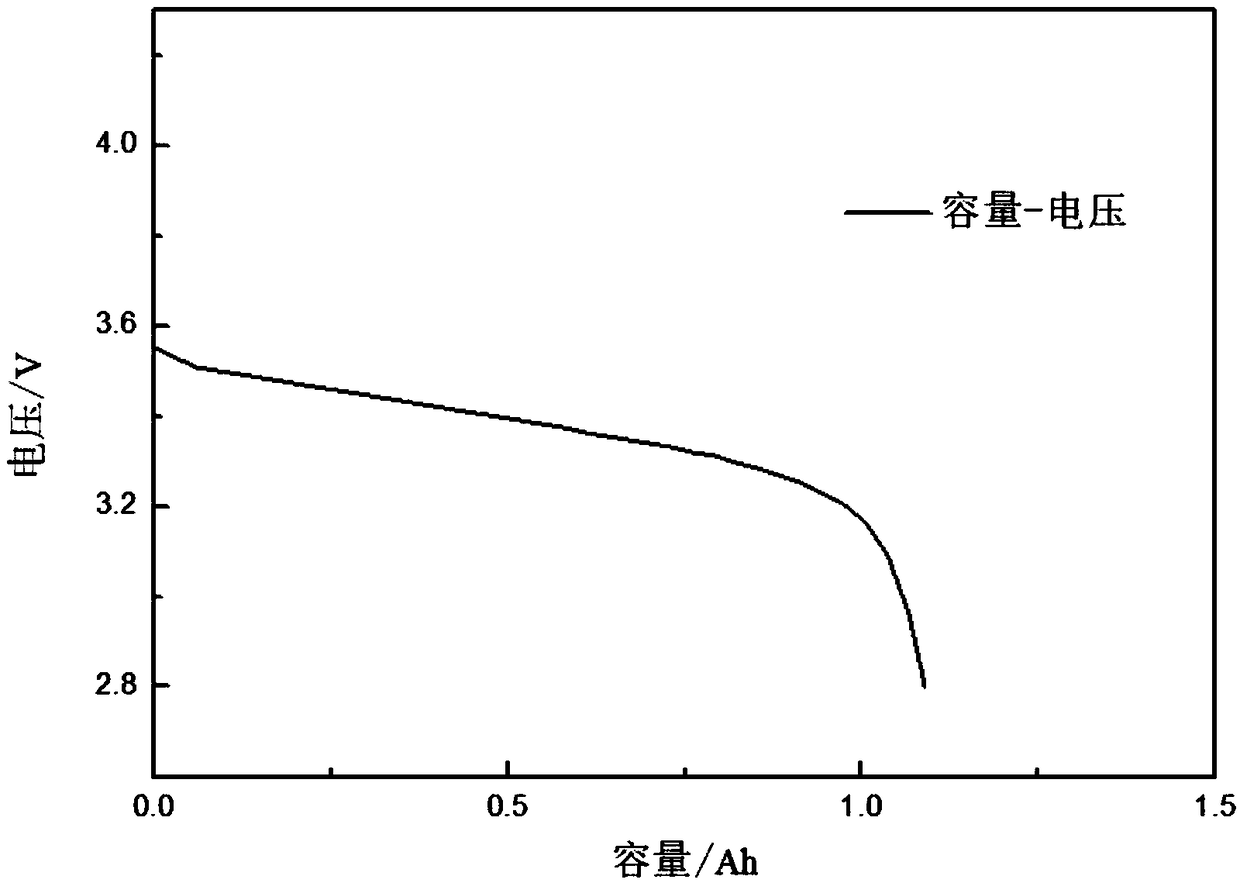
[0037] a. Put the 8Ah soft-packed battery cell at 25℃ for 10h, discharge it to 2.8V with 1C current, and let it stand for 1h; charge it with 1C constant current to 4.2V, then transfer to constant voltage charging until the current ≤0.05C to stop, Let stand for 1h, then discharge to 2.8V at 1C, stand for 1h, cycle the above charging and discharging process for 3 weeks, the discharge curve of the last week is as follows figure 1 As shown, the discharge capacity of 8.02 Ah in the last week is recorded as Ca. ;

[0038] b. Put the battery cell in a 0℃ low temperature environment and let it stand for 10 hours;

[0039] c. Charge the battery in step b with a 1C high-rate current to 4.2V at the 0°C, then switch to constant-voltage charging until the current is ≤0.05C, stop, ...

Embodiment 2

[0045] The low temperature environment was changed to -10°C, and the remaining experimental conditions were the same as in Example 1. Ca was obtained as 8.08Ah, Cb was 0.78Ah, and the amount of lithium deposited in the negative electrode at -10°C was calculated. The results are shown in Table 1.

Embodiment 3

[0047] The low temperature environment was changed to -20°C, and the other experimental conditions were the same as in Example 1. Ca was obtained as 8.05Ah and Cb was 1.08Ah. The amount of lithium deposited in the negative electrode at -20°C was calculated. The results are shown in Table 1.

[0048] Table 1 shows the positive electrode unsaturation of lithium-ion batteries under different low-temperature environments, that is, the amount of lithium released from the negative electrode;

[0049] Example


PUM


Abstract

The invention discloses a quantification method for lithium deposition in a lithium ion battery anode. Lithium desorbed from a positive electrode forms a lithium dendrite in a negative electrode by low-temperature large-rate charging, and the lithium dendrite formed on the surface of the negative electrode after being desorbed from the positive electrode is quantized by subsequent lithium embeddedin a positive electrode material. According to a disassembling method for a low-risk cell, the lithium deposition amount in the negative electrode is quantified, thereby reducing the risk of operation. The test method is simple, and the test result is brief and reliable, so that the method is practical and feasible.

Description

Technical field [0001] The invention belongs to the field of lithium ion batteries, and in particular relates to a method for quantifying lithium evolution from negative electrodes of lithium ion batteries. Background technique [0002] As the popularity of electric vehicles increases, our performance requirements for lithium-ion power batteries are getting higher and higher. However, there are still many performances of lithium ion that cannot meet the needs of the public. One of them is low-temperature charging performance. At low temperatures (below 0°C), lithium-ion power batteries will deposit metal lithium on the negative electrode of the battery during the charging process. Not only affects the battery capacity, but also reduces the safety of the battery. If the battery is directly disassembled to analyze the metal lithium content on the negative electrode surface in a fully charged state, it is not only difficult to operate, but also faces the oxidation and decomposition...

Claims


Application Information

Patent Timeline
IPC IPC(8): G01R31/385G01R31/392
Inventor 邵素霞李亚金王蓉蓉吴欢欢冷飞喜姚丹
Owner HEFEI GUOXUAN HIGH TECH POWER ENERGY
Learn More