
A rudder surface clearance wind tunnel test simulation device

A wind tunnel test and simulation device technology, applied in the field of aerospace engineering, can solve problems such as easy mutual interference, easy test accidents, and increase the difficulty of main beam design, and achieve accurate boundary condition simulation, easy modification and control, and systematic effect of small error

Active Publication Date: 2020-07-14
CHINA ACAD OF AEROSPACE AERODYNAMICS
View PDF6 Cites 0 Cited by
  • Summary
  • Abstract
  • Description
  • Claims
  • Application Information

AI Technical Summary

Problems solved by technology

[0005] (1) Since the same main beam is used to simulate the bending and torsional stiffness of the model, it is easy for the two to interfere with each other, and the boundary condition model is not easy to be accurate
[0006] (2) The gap nonlinear phenomenon that cannot simulate the boundary conditions of the model
[0007] (3) Using the same main beam to simulate the bending and torsional stiffness of the model, the design work will inevitably encounter the coupling of two data quantities, which increases the difficulty of the main beam design
[0008] (4) The main beam lacks corresponding limit and protection devices. When the model vibrates violently, test accidents are prone to occur

Method used


Image

  • A rudder surface clearance wind tunnel test simulation device
  • A rudder surface clearance wind tunnel test simulation device
  • A rudder surface clearance wind tunnel test simulation device

Examples


Embodiment Construction

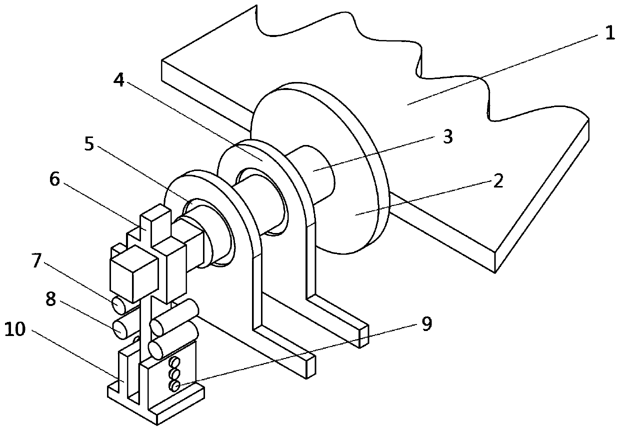
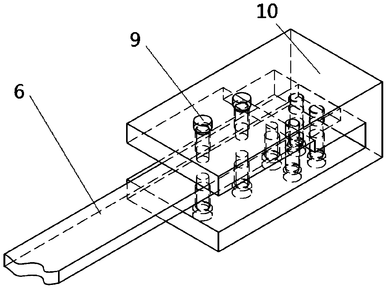
[0031] Such as figure 2 , image 3 , Figure 4 As shown, the present invention includes: 1 model, 2 model fixed flange, 3 model main shaft, 4 model fixed sleeve, 5 bearing, 6 torsion spring plate, 7 emergency limit nail, 8 model protection column, 9 gap control screw / Bolt, 10 fixed base

[0032] One end of the model fixing flange 2 is fixedly connected to the model 1, and the other end is fixedly connected to the model main shaft 3. The middle section of the main shaft 3 of the model is a circular section, and the two ends are rectangular sections. The rectangular section beam connected to the torsion spring plate is used for fixing, and the rectangular section beam connected to the flange is used to simulate the bending stiffness of the model. Through the torsion spring plate 6 The bending realizes the control of the torsional stiffness of the model. Bearing 5 is installed in model fixed cover 4 inside, and model main shaft 3 passes two bearings 5. The inner diameter o...


PUM


Abstract

The invention provides a control surface gap wind tunnel test simulation device. One end of a model spindle (3) is fixedly connected to a control surface model (1) through a model fixing flange (2), and the other end of the model spindle (3) is fixedly connected to a torsion spring plate (6). The free end of the torsion spring plate (6) is inserted into the recess of a fixed base (10) with a gap therebetween. The gap is adjustable by a gap control screw / bolt (9) mounted on the fixed base (10). The torsional stiffness of the model is controlled by the bending of the torsion spring plate (6). The deformation of the torsion spring plate (6) is restricted by a model guard column (8). A bearing (5) is mounted inside a model fixing sleeve (4). The model spindle (3) passes through two bearings (5), and the model fixing sleeve (4) is used to fix the degree of freedom other than the spindle torsion. The present invention enables simulation of linear and non-linear conditions by adjusting the size of the gap.

Description

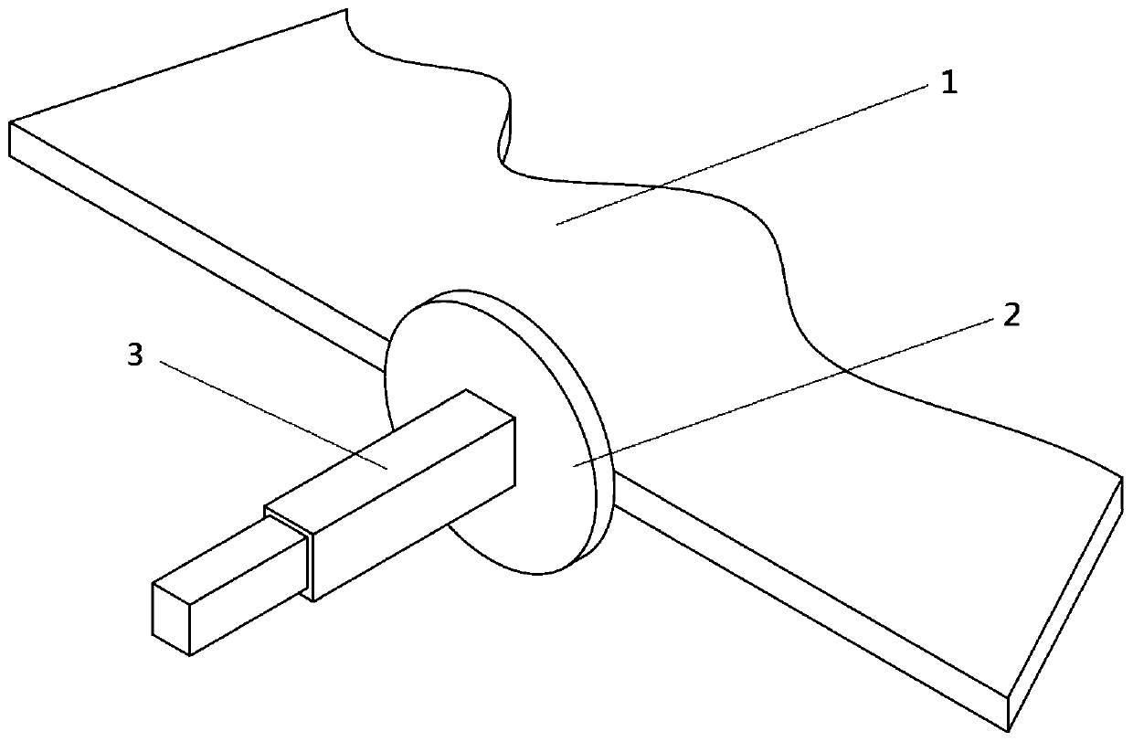
technical field [0001] The invention relates to a wind tunnel test fixture and belongs to the field of aerospace engineering. Background technique [0002] When conducting aircraft wing rudder surface tests, it is often necessary to fix the model. The fixed end of the model needs to ensure the safety of the model, and also needs to simulate the bending stiffness, torsional stiffness, and boundary conditions of some nonlinear gaps of the model. This rudder surface The design of the gap wind tunnel test simulator is based on the above considerations. [0003] Such as figure 1 As shown, the existing wind tunnel rudder surface model fixing device mainly includes: model 1, flange plate 2, and model main beam 3. Among them, the model 1 is fixed with the flange 2, the main beam 3 of the model is fixedly connected with the flange 2, and the main beam of the model is used to simulate the bending stiffness and torsional stiffness. [0004] The existing wind tunnel rudder surface mo...

Claims


Application Information

Patent Timeline
Patent Type & Authority Patents(China)
IPC IPC(8): G01M9/04
CPCG01M9/04
Inventor 付志超刘子强陈占军吕计男侯英昱
Owner CHINA ACAD OF AEROSPACE AERODYNAMICS
Learn More