A room cement slurry paving equipment
A cement slurry and room technology, which is applied in the direction of construction and building construction, can solve the problems of easy numbness, excessive manpower, and cost, and achieve the effect of preventing random rotation, upward movement, and damage to equipment
- Summary
- Abstract
- Description
- Claims
- Application Information
AI Technical Summary
Problems solved by technology
Method used
Image

Examples
Embodiment 1
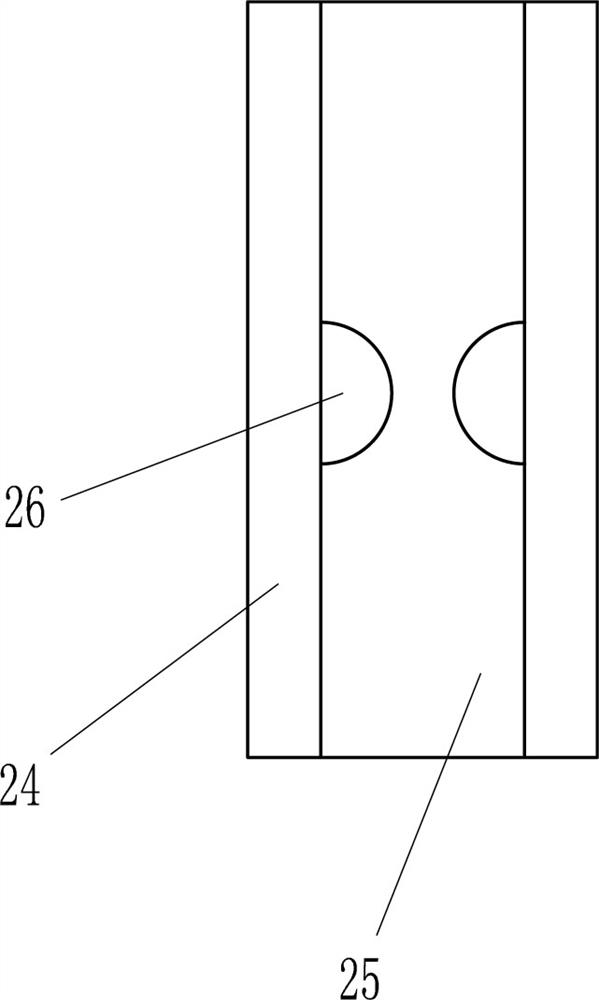
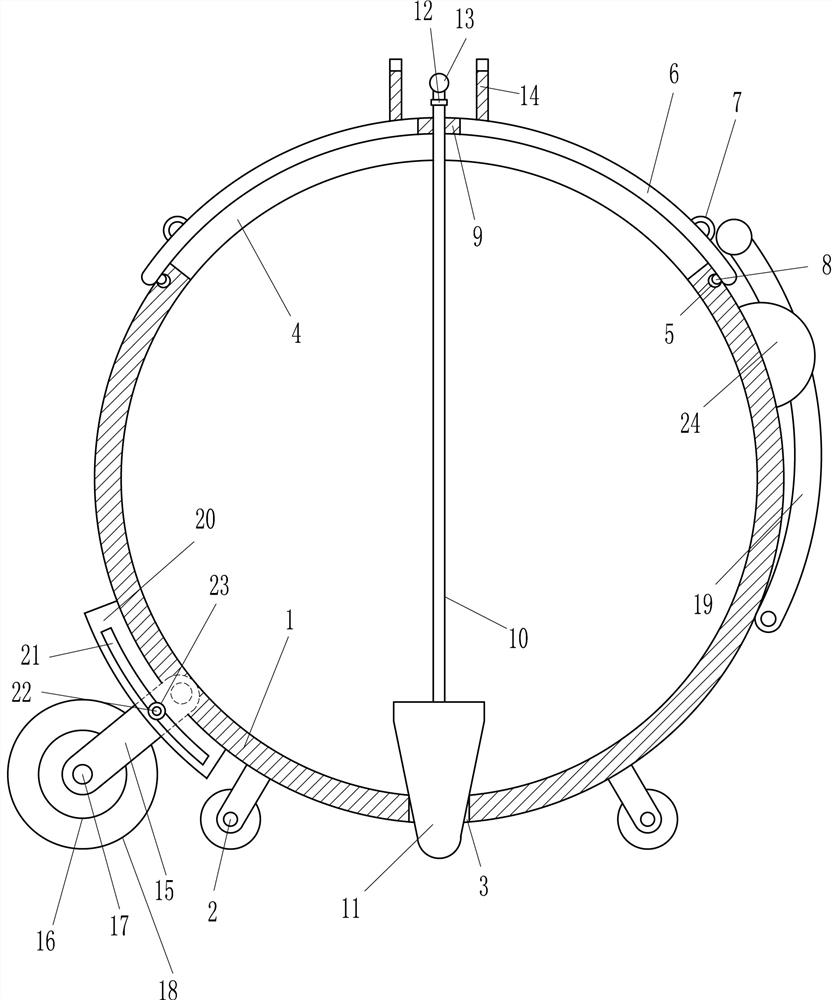
[0016] A room grout paving equipment such as Figure 1-2 As shown, it includes box body 1, wheel 2, cover plate 6, pull ring 7, card ball 8, guide sleeve 9, connecting rod 10, plug 11, swivel joint 12, T-shaped tie rod 13, concave plate 14, connection Plate 15, bearing seat 16, rotating shaft 17, cylinder 18 and arc-shaped pull rod 19, the left and right sides of the bottom of the box body 1 are equipped with wheels 2, the middle of the bottom of the box body 1 has a discharge hole 3, and the upper wall of the box body 1 is opened. There is a feed hole 4, the box body 1 on the left and right sides of the feed hole 4 is provided with a card slot 5, the upper side of the box body 1 is provided with a cover plate 6, the cover plate 6 is located above the feed hole 4, and the top of the cover plate 6 The left and right sides of the cover plate 6 are provided with pull rings 7, the left and right sides of the bottom of the cover plate 6 are provided with clamping balls 8, the clamp...
Embodiment 2
[0018] A room grout paving equipment such as Figure 1-2 As shown, it includes box body 1, wheel 2, cover plate 6, pull ring 7, card ball 8, guide sleeve 9, connecting rod 10, plug 11, swivel joint 12, T-shaped tie rod 13, concave plate 14, connection Plate 15, bearing seat 16, rotating shaft 17, cylinder 18 and arc-shaped pull rod 19, the left and right sides of the bottom of the box body 1 are equipped with wheels 2, the middle of the bottom of the box body 1 has a discharge hole 3, and the upper wall of the box body 1 is opened. There is a feed hole 4, the box body 1 on the left and right sides of the feed hole 4 is provided with a card slot 5, the upper side of the box body 1 is provided with a cover plate 6, the cover plate 6 is located above the feed hole 4, and the top of the cover plate 6 The left and right sides of the cover plate 6 are provided with pull rings 7, the left and right sides of the bottom of the cover plate 6 are provided with clamping balls 8, the clamp...
Embodiment 3
[0021] A room grout paving equipment such as Figure 1-2 As shown, it includes box body 1, wheel 2, cover plate 6, pull ring 7, card ball 8, guide sleeve 9, connecting rod 10, plug 11, swivel joint 12, T-shaped tie rod 13, concave plate 14, connection Plate 15, bearing seat 16, rotating shaft 17, cylinder 18 and arc-shaped pull rod 19, the left and right sides of the bottom of the box body 1 are equipped with wheels 2, the middle of the bottom of the box body 1 has a discharge hole 3, and the upper wall of the box body 1 is opened. There is a feed hole 4, the box body 1 on the left and right sides of the feed hole 4 is provided with a card slot 5, the upper side of the box body 1 is provided with a cover plate 6, the cover plate 6 is located above the feed hole 4, and the top of the cover plate 6 The left and right sides of the cover plate 6 are provided with pull rings 7, the left and right sides of the bottom of the cover plate 6 are provided with clamping balls 8, the clamp...
PUM
 Abstract
Description
Claims
Application Information
 - R&D
- Intellectual Property
- Life Sciences
- Materials
- Tech Scout
- Unparalleled Data Quality
- Higher Quality Content
- 60% Fewer Hallucinations
Browse by: Latest US Patents, China's latest patents, Technical Efficacy Thesaurus, Application Domain, Technology Topic, Popular Technical Reports.
© 2025 PatSnap. All rights reserved.Legal|Privacy policy|Modern Slavery Act Transparency Statement|Sitemap|About US| Contact US: help@patsnap.com