Room cement paste flattening equipment
A kind of cement slurry and room technology, applied in the direction of construction, building structure, etc., can solve the problems of easy foot numbness, multi-manpower, waste and other problems, and achieve the effect of preventing upward movement, preventing random rotation, and preventing damage to equipment
- Summary
- Abstract
- Description
- Claims
- Application Information
AI Technical Summary
Problems solved by technology
Method used
Image

Examples
Embodiment 1
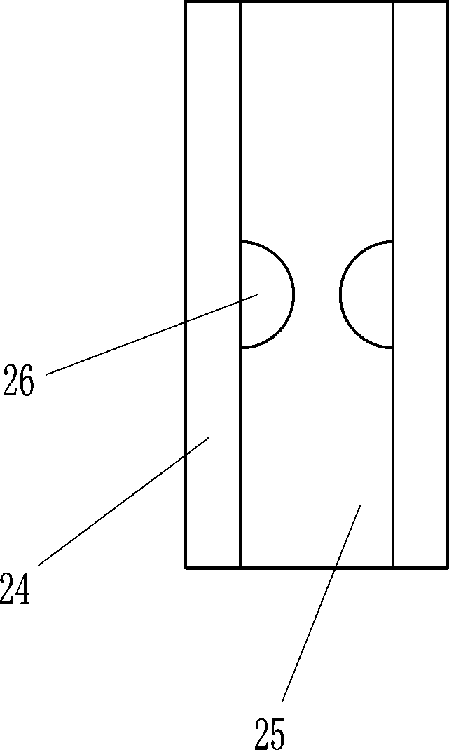
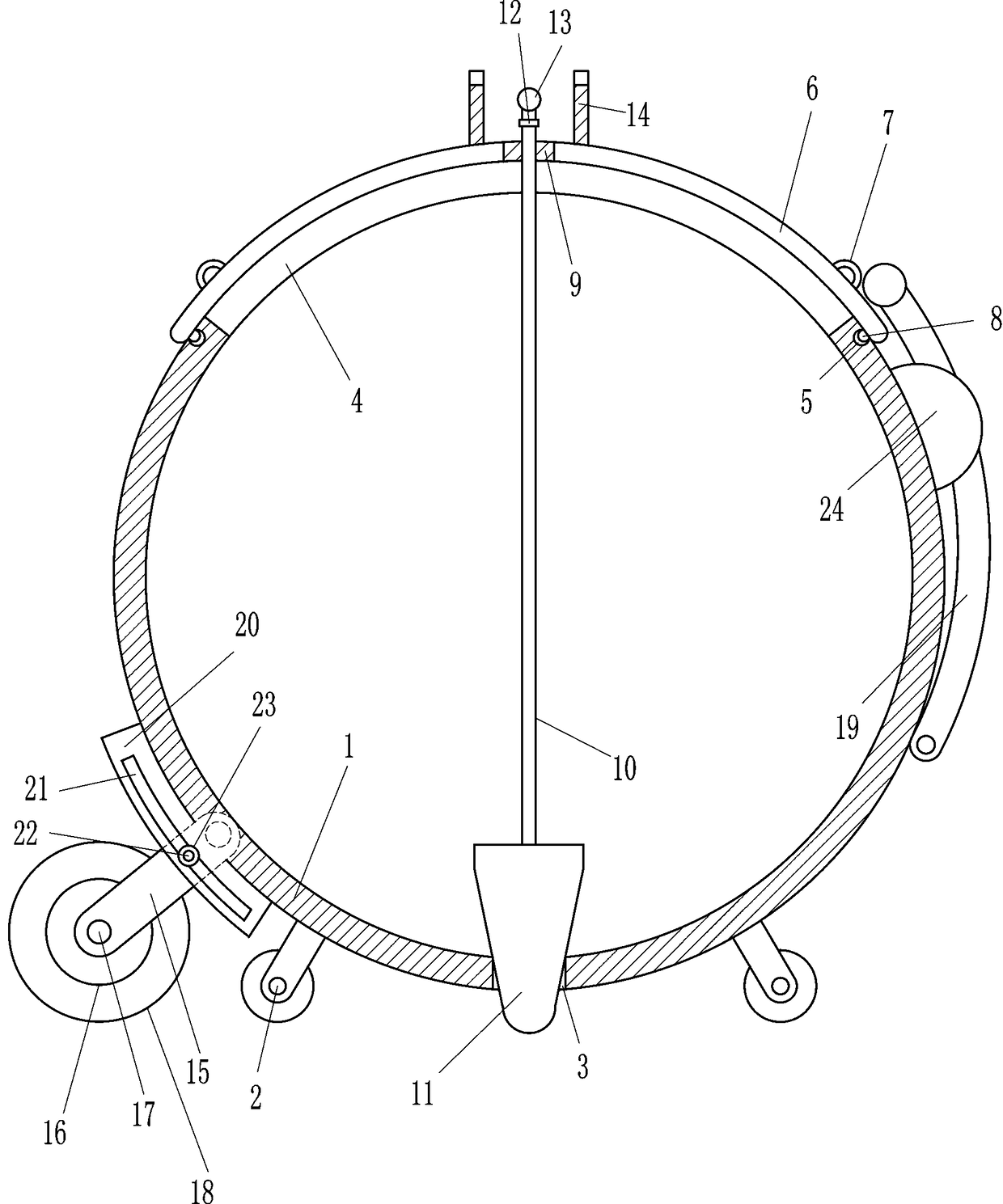
[0016] A room grout paving equipment such as Figure 1-2 As shown, it includes box body 1, wheel 2, cover plate 6, pull ring 7, card ball 8, guide sleeve 9, connecting rod 10, plug 11, swivel joint 12, T-shaped tie rod 13, concave plate 14, connection Plate 15, bearing seat 16, rotating shaft 17, cylinder 18 and arc-shaped pull rod 19, the left and right sides of the bottom of the box body 1 are equipped with wheels 2, the middle of the bottom of the box body 1 has a discharge hole 3, and the upper wall of the box body 1 is opened. There is a feed hole 4, the box body 1 on the left and right sides of the feed hole 4 is provided with a card slot 5, the upper side of the box body 1 is provided with a cover plate 6, the cover plate 6 is located above the feed hole 4, and the top of the cover plate 6 The left and right sides of the cover plate 6 are provided with pull rings 7, the left and right sides of the bottom of the cover plate 6 are provided with clamping balls 8, the clamp...
Embodiment 2
[0018] A room grout paving equipment such as Figure 1-2 As shown, it includes box body 1, wheel 2, cover plate 6, pull ring 7, card ball 8, guide sleeve 9, connecting rod 10, plug 11, swivel joint 12, T-shaped tie rod 13, concave plate 14, connection Plate 15, bearing seat 16, rotating shaft 17, cylinder 18 and arc-shaped pull rod 19, the left and right sides of the bottom of the box body 1 are equipped with wheels 2, the middle of the bottom of the box body 1 has a discharge hole 3, and the upper wall of the box body 1 is opened. There is a feed hole 4, the box body 1 on the left and right sides of the feed hole 4 is provided with a card slot 5, the upper side of the box body 1 is provided with a cover plate 6, the cover plate 6 is located above the feed hole 4, and the top of the cover plate 6 The left and right sides of the cover plate 6 are provided with pull rings 7, the left and right sides of the bottom of the cover plate 6 are provided with clamping balls 8, the clamp...
Embodiment 3
[0021] A room grout paving equipment such as Figure 1-2 As shown, it includes box body 1, wheel 2, cover plate 6, pull ring 7, card ball 8, guide sleeve 9, connecting rod 10, plug 11, swivel joint 12, T-shaped tie rod 13, concave plate 14, connection Plate 15, bearing seat 16, rotating shaft 17, cylinder 18 and arc-shaped pull rod 19, the left and right sides of the bottom of the box body 1 are equipped with wheels 2, the middle of the bottom of the box body 1 has a discharge hole 3, and the upper wall of the box body 1 is opened. There is a feed hole 4, the box body 1 on the left and right sides of the feed hole 4 is provided with a card slot 5, the upper side of the box body 1 is provided with a cover plate 6, the cover plate 6 is located above the feed hole 4, and the top of the cover plate 6 The left and right sides of the cover plate 6 are provided with pull rings 7, the left and right sides of the bottom of the cover plate 6 are provided with clamping balls 8, the clamp...
PUM
 Abstract
Description
Claims
Application Information
 - R&D
- Intellectual Property
- Life Sciences
- Materials
- Tech Scout
- Unparalleled Data Quality
- Higher Quality Content
- 60% Fewer Hallucinations
Browse by: Latest US Patents, China's latest patents, Technical Efficacy Thesaurus, Application Domain, Technology Topic, Popular Technical Reports.
© 2025 PatSnap. All rights reserved.Legal|Privacy policy|Modern Slavery Act Transparency Statement|Sitemap|About US| Contact US: help@patsnap.com