
Test tube capable of moving liquid at upper end and test tube assembly

A test tube and pipetting technology, applied in the field of laboratory containers, can solve the problems of cross-contamination, inconvenient use, etc., and achieve the effect of convenient pipetting, avoiding contamination, and low proficiency requirements

Active Publication Date: 2019-02-01
ZHENGZHOU VIRIGE BIOTECH
View PDF4 Cites 1 Cited by
  • Summary
  • Abstract
  • Description
  • Claims
  • Application Information

AI Technical Summary

Problems solved by technology

[0005] The purpose of the present invention is to provide a test tube that can be pipetted at the upper end, so as to solve the problem that the existing test tube adopts a pipette tip that needs to be inserted into the bottom of the tube to transfer liquid, which is prone to cross contamination and inconvenient to use

Method used


Image

  • Test tube capable of moving liquid at upper end and test tube assembly
  • Test tube capable of moving liquid at upper end and test tube assembly
  • Test tube capable of moving liquid at upper end and test tube assembly

Examples


Embodiment Construction

[0063] The present invention will be further described below in conjunction with accompanying drawing.

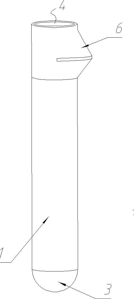
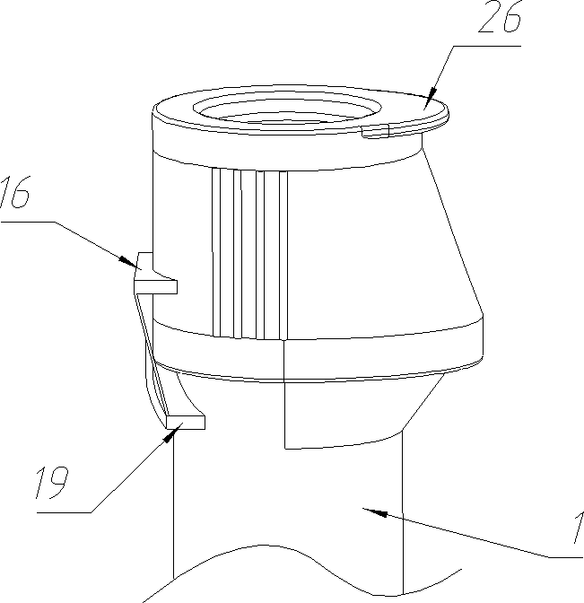
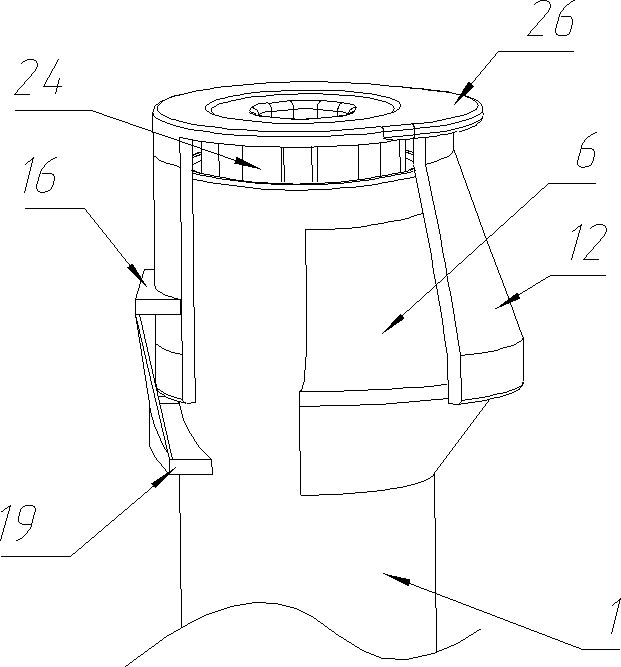
[0064] Embodiment 1 of the test tube that can be pipetted at the upper end in the present invention is as Figure 1-Figure 3 As shown, the lower part is a cylindrical tube body 1. The tube body 1 includes a tube side wall 2 and a round-bottomed tube bottom 3 closed at the lower end of the tube side wall 2. The upper end of the tube side wall 2 is provided with a nozzle 4. The upper part of the side wall 2 is provided with a wall bulge 6 that bulges toward the radial side of the pipe body 1 below the nozzle 4. The wall bulge 6 is a unidirectional wall bulge. The inner cavity surrounded by the side wall 2 forms a concave cavity 5 for the liquid inside the tube body 1 to flow into, and the concave cavity 5 is a single-sided concave cavity. In the axial direction of the tube body 1, the radial size of the wall bulge 6 gradually decreases from the middle to the upper and lower ...


PUM


Abstract

The invention relates to the field of laboratory containers, in particular to a test tube capable of transferring a liquid at the upper end and a test tube assembly. The test tube comprises a tube body, wherein the lower end of the tube body is a closed tube bottom, a tube opening is formed in the upper end of the tube body, a wall bulge protruding towards the radial outer side of the tube body isarranged below the tube opening of the upper part of the tube body, and the wall bulge is provided with a concave cavity for allowing the liquid in the test tube to flow into the test tube when beingoverturned to a low position. The test tube assembly comprises the test tube capable of transferring the liquid at the upper end and a flip type tube cap which covers the upper end including the wallbulge of the test tube. According to the scheme, the problems of inconvenience caused for the reason that when the existing test tube is used, a pipette or a suction head needs to be inserted into the tube bottom to transfer the liquid and cross contamination which is easily caused for the reason that a liquid-transferring machine rod is inserted into the tube body can be solved, and the flip type test tube assembly can avoid the risk of falling and mismatch of a split type tube cap, and is convenient to operate.

Description

technical field [0001] The invention relates to the field of laboratory containers, in particular to a test tube capable of pipetting liquid from the upper end and a test tube assembly. Background technique [0002] A test tube is a small container made of glass or transparent plastic tubes commonly used in chemical laboratories and life science laboratories. The test tubes used for the cultivation of biological cells or microorganisms are also called culture tubes. The test tube usually includes a tube body, the lower end of the tube body is closed as a tube bottom, and the upper end of the tube body is provided with a nozzle. The nozzle has a flat mouth form and a rolled mouth form. The rolled mouth form means that the edge of the nozzle protrudes slightly to the outside to form a flange with an outer diameter larger than that of other parts of the pipe body, which is convenient for the clamping of the pipe body and the fixing of the pipe cover. The lock is not easy to fa...

Claims


Application Information

Patent Timeline
IPC IPC(8): C12M1/24C12M1/00B01L3/14
CPCC12M23/08C12M23/38B01L3/5082B01L2200/16B01L2200/141Y02A50/30
Inventor 韩志强
Owner ZHENGZHOU VIRIGE BIOTECH
Learn More