Swinging frame type rear wheel driving structure for spreading machine
A technology of rear-wheel drive and paver, applied in the direction of suspension, elastic suspension, road, etc., can solve the problems of rear-wheel drive structure anti-skid performance and poor road adaptability, affecting product flexibility, poor vehicle turning performance, etc. To achieve the effect of ensuring steering performance and anti-skid performance, improving product flexibility and large driving capacity
- Summary
- Abstract
- Description
- Claims
- Application Information
AI Technical Summary
Problems solved by technology
Method used
Image

Examples
Embodiment 1
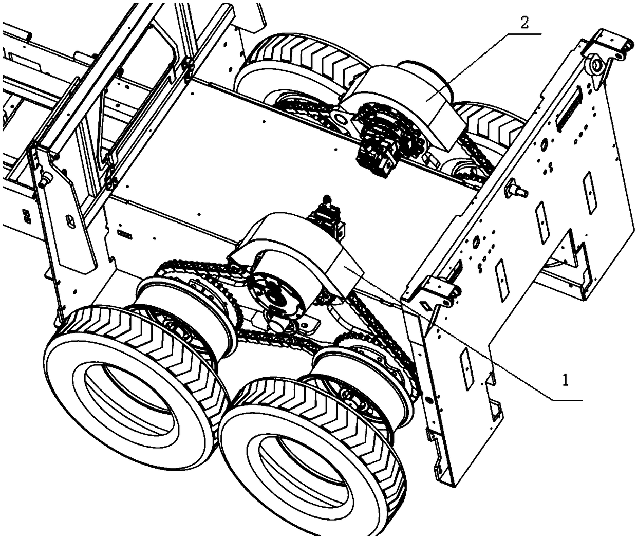
[0031] Such as Figure 1-2 As shown, the swing frame type rear wheel drive structure for paver in the embodiment of the present invention includes a first drive unit 1 and a second drive unit 2; the first drive unit 1 is arranged opposite to the second drive unit 2, And both have the same structure, including:
[0032] A bracket 3, the bracket 3 is provided with a hinge hole;
[0033] Revolving shaft 9, described revolving shaft 9 passes through the hinged hole on described support 3, is arranged perpendicular to described support 3, is used for supporting 3 to rotate around it; on the fuselage of the machine;
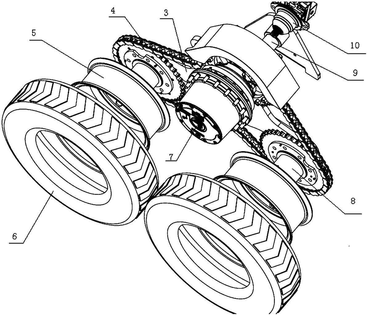
[0034] Drive assembly, the drive assembly is located on the support 3; the drive assembly includes a drive motor 10, a speed reducer 7 and a transmission device 4 arranged in sequence; the output of the transmission device 4 is connected to the first rotating assembly It is connected with one end of the wheel shaft 8 in the second rotating assembly; in the embodimen...
Embodiment 2
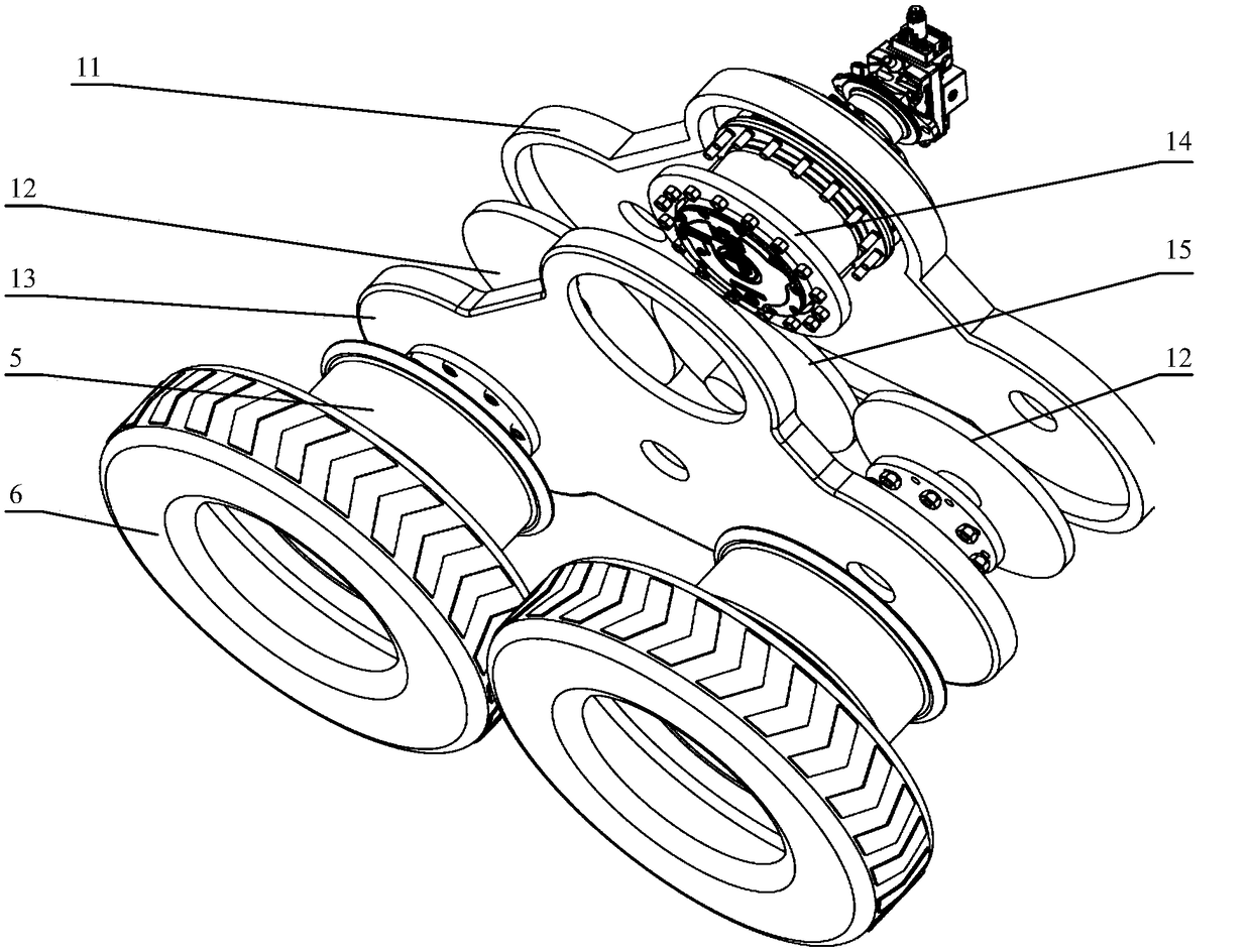
[0038] Based on the same inventive concept as in Embodiment 1, in the embodiment of the present invention, the drive assembly is a gear transmission, including an inner case 11 of the transmission case and an outer case 13 of the transmission case, such as image 3 shown.
[0039] In a specific implementation of the embodiment of the present invention, the transmission device includes a driving gear 14, an idler gear 15 and 2 gears arranged in the transmission box inner box 11 and the transmission box outer box 13. A driven gear 12; the drive gear 14 is connected with the output of the speed reducer 7; the idler gear 15 is arranged between the drive gear 14 and 2 driven gears 12; each driven gear 12 is connected with the drive gear 12 respectively; One end of the axle 8 in the first rotating assembly and the second rotating assembly is connected; when the driving gear 14 receives the driving force, it drives the idler gear 15 to rotate, and the idler gear 15 drives the driven ...
PUM
 Abstract
Description
Claims
Application Information
 - R&D
- Intellectual Property
- Life Sciences
- Materials
- Tech Scout
- Unparalleled Data Quality
- Higher Quality Content
- 60% Fewer Hallucinations
Browse by: Latest US Patents, China's latest patents, Technical Efficacy Thesaurus, Application Domain, Technology Topic, Popular Technical Reports.
© 2025 PatSnap. All rights reserved.Legal|Privacy policy|Modern Slavery Act Transparency Statement|Sitemap|About US| Contact US: help@patsnap.com