
Test tube shaking device

A test tube and driving seat technology, applied in the field of experimental equipment, can solve the problems of poor mixing effect, low efficiency, small shaking amplitude, etc., and achieve the effect of increasing the shaking amplitude, improving the shaking effect, and increasing the centrifugal force.

Inactive Publication Date: 2019-02-01
泉州医学高等专科学校
View PDF4 Cites 0 Cited by
  • Summary
  • Abstract
  • Description
  • Claims
  • Application Information

AI Technical Summary

Problems solved by technology

[0002] In the process of experiment or product production, it is often necessary to mix the sample in the test tube. In order to quickly realize the uniform mixing of the sample, the test tube needs to be shaken. In the prior art, most of the above work is done manually, with low efficiency and poor mixing effect.
For example: Chinese utility model application number 201720824414.5 discloses a test tube shaking device for an analyzer, including a driving seat, a wheel passive drive structure located on one side of the driving seat, and a drive that can drive the driving seat to reciprocate. mechanism, the driving seat is provided with a rotating shaft, and the rotating shaft is provided with a test tube clamping device and a rotating wheel that can cooperate with the passive driving structure of the rotating wheel to drive the rotating shaft to rotate when the driving seat reciprocates. Because the rotation center of this device is located at the clamping position when shaking, that is, on the test tube, the shaking range is small and the mixing effect is poor

Method used


Image

  • Test tube shaking device
  • Test tube shaking device

Examples


Embodiment

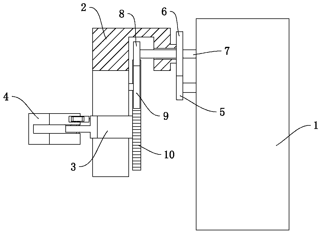
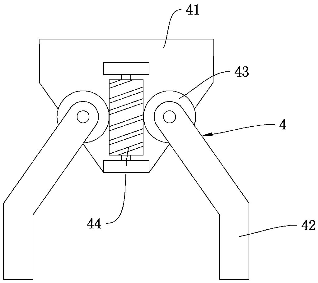
[0018] Example: such as figure 1 and figure 2 As shown, a test tube shaking device includes a supporting base 1, a driving base 2 and a clamping mechanism 4, the driving base 2 is rotatably mounted on the supporting base 1 through a fixed shaft 7, and the clamping mechanism 4 is arranged on the driving base 2 Rotate with driving seat 2 on. The drive base 2 is fixed with a transmission gear 6 , and the drive base 2 and the transmission gear 6 rotate synchronously relative to the fixed shaft 7 and the support base 1 . The supporting base 1 is provided with a driving gear 5 meshing with the transmission gear 6 and a driving mechanism for driving the driving gear 5 forward and reverse. The driving mechanism includes a reduction gear, a motor and a power supply arranged in the support base 1. Several reduction gears are meshed with each other for transmission. At least one reduction gear rotates coaxially with the driving gear 5. The motor adopts a servo motor, and the circuit a...


PUM


Abstract

The invention relates to the technical field of experimental equipment and particularly to a test tube shaking device. The test tube shaking device comprises a support base, a driving base and a clamping mechanism. The clamping mechanism is arranged on the driving base. The driving base is rotatingly installed on the support base through a fixed shaft. A transmission gear is fixedly arranged on the driving base. A driving gear meshed with the transmission gear and a driving mechanism driving the driving gear to rotate forward and backward are arranged on the support base. The clamping mechanism is arranged one side, opposite to the support base, of the driving base and is located below a rotation center of the driving base. The test tube shaking device can fast and uniformly shake a samplein the test tube and save the time and labor of an experimenter. The test tube forms a certain distance from the rotation center so that the shaking amplitude of the test tube is increased, the centrifugal force on the sample in the test tube is increased and the shaking efficiency and effect are improved.

Description

technical field [0001] The invention relates to the technical field of experimental equipment, in particular to a test tube shaking device. Background technique [0002] In the process of experiment or product production, it is often necessary to mix the samples in the test tube. In order to quickly realize the uniform mixing of the samples, the test tube needs to be shaken. In the prior art, the above work is mostly done manually, with low efficiency and poor mixing effect. For example: Chinese utility model application number 201720824414.5 discloses a test tube shaking device for an analyzer, including a driving seat, a wheel passive drive structure located on one side of the driving seat, and a drive that can drive the driving seat to reciprocate. mechanism, the driving seat is provided with a rotating shaft, and the rotating shaft is provided with a test tube clamping device and a rotating wheel that can cooperate with the passive driving structure of the rotating wheel...

Claims


Application Information

Patent Timeline
Patent Type & Authority Applications(China)
IPC IPC(8): B01F11/00
CPCB01F31/20B01F31/201B01F2101/23
Inventor 曾燕坤王翠玲邱国宾吴玮林瑞琪
Owner 泉州医学高等专科学校
Learn More