Malposition alignment and separation conveying device for special-shaped glue strips of shoe edges

A conveying device and rubber strip technology, applied in footwear, heel pads, shoe-making machinery, etc., can solve problems such as affecting product quality, unguaranteed product quality, and product crushing, and improve product production. The effect of efficiency and product quality

Inactive Publication Date: 2019-02-01
JIHUA 3517 RUBBER PROD
View PDF0 Cites 0 Cited by
  • Summary
  • Abstract
  • Description
  • Claims
  • Application Information

AI Technical Summary

Problems solved by technology

[0003] After cutting the S-shaped edge of the special-shaped rubber strips on the existing shoe edge, it is necessary to align the two adjacent rubber strips and then go through the cutting machine for cutting operation. However, after the alignment of the two adjacent rubber strips, the arc-shaped protrusions often The situation of superimposing together causes the product to be crushed after passing through the roller on the cutting machine, which seriously affects the quality of the product, and there is a certain viscosity between the rubber strips, which need to be separated. In the actual operation process , the strips are separated by hand and then cut by a cutting machine. The separation efficiency is not high, and the quality of the product cannot be guaranteed. Therefore, it is necessary to develop a conveying device for the heterotopic alignment and separation of special-shaped rubber strips on the edge of shoes.

Method used


Image

  • Malposition alignment and separation conveying device for special-shaped glue strips of shoe edges
  • Malposition alignment and separation conveying device for special-shaped glue strips of shoe edges
  • Malposition alignment and separation conveying device for special-shaped glue strips of shoe edges

Examples


Embodiment Construction

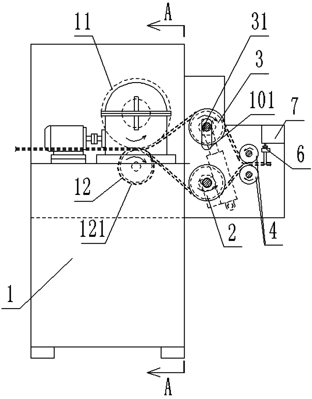
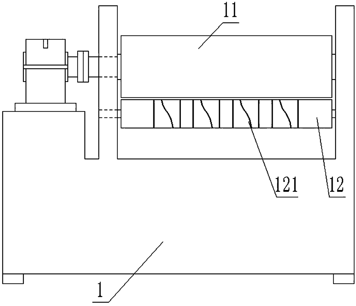
[0020] In order to enable those skilled in the art to better understand the technical solution of the present invention, the present invention will be described in detail below in conjunction with the accompanying drawings. The description in this part is only exemplary and explanatory, and should not have any limiting effect on the protection scope of the present invention. .

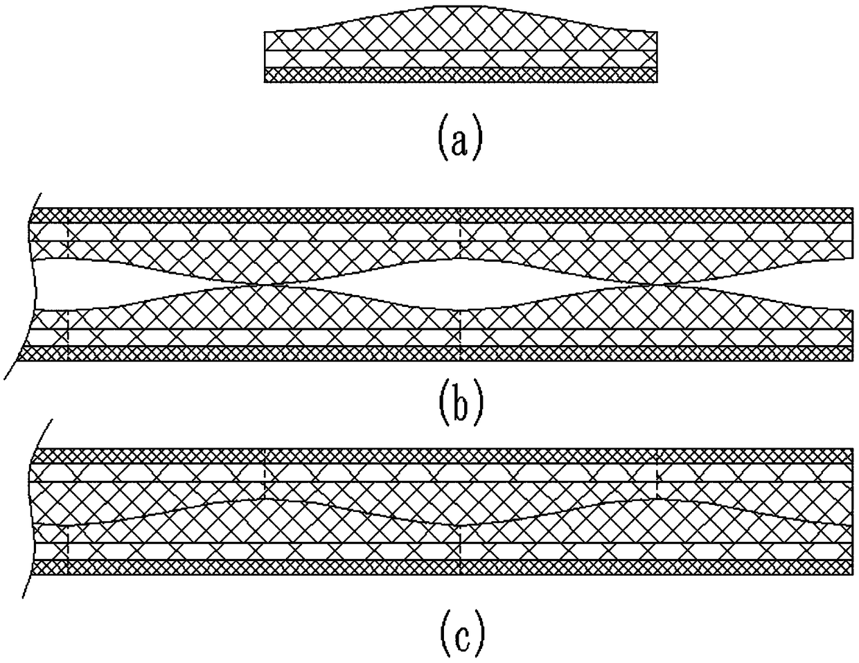
[0021] like Figure 2-7 As shown, the specific structure of the present invention is as follows: comprising a hobbing and cutting machine main body 1, a horizontally rotatable driving roller 11 and a driven roller 12 are arranged on the hobbing and cutting machine main body 1, and the outer cylindrical surface of the driven roller 12 is pressed Tight driving roller 11, is provided with hob 121 on its circumference, and described hob 121 is arranged in multiple groups, and the described hob 121 of each group is made up of straight two edge cutters and an S-shaped cutter, and S-shaped The cutting knife ...


PUM


Abstract

The invention discloses a malposition alignment and separation conveying device for special-shaped glue strips of shoe edges. The device comprises a main rolling cutting machine body, the main rollingcutting machine body is provided with a drive roller and a driven roller, rolling cutters are arranged on the outer circumference of the driven roller, and a flat guiding roller A and a flat guidingroller B which can horizontally rotate are arranged at the discharging end of the main rolling cutting machine body, and the flat guiding roller B can be vertically and movably adjusted; guiding grooves are formed in the circumferences of the flat guiding rollers, and the spreading shapes of the cylinder faces of the guiding grooves are matched with the shoe glue strips; a guiding roller and an electric push rod for lifting adjustment of the flat guiding roller B are further arranged at the side of the main rolling cutting machine body, an adjustment device and a controller are arranged at thedischarging end of the guiding roller, and the adjustment device is used for detecting the deviation amount of every two adjacent shoe glue strips; the controller is used for controlling extension and retraction of the electric push rod. According to the malposition alignment and separation conveying device for the special-shaped glue strips of the shoe edges, the adjacent shoe glue stirps are separated, subjected to malposition alignment and then conveyed to a cut-off machine, micro alignment, correction and adjustment can be conducted, and the product quality is guaranteed.

Description

technical field [0001] The invention belongs to the field of shoe production equipment, and specifically relates to a conveying device for different-position alignment and separation of special-shaped rubber strips on shoe edges. Background technique [0002] The shoe edge, also known as the rubber shoe skirt, refers to the flat rubber strip that is attached to the side of the rubber shoe, connecting the sole and the upper part, and has decorative and protective functions. Due to production needs, a special-shaped shoe edge rubber strip (such as figure 1 shown), where a is the required shoe edge special-shaped rubber strip, which is in the shape of an arc-shaped protrusion in the middle and low ends. The existing raw material of the shoe edge special-shaped rubber strip is in the form of a whole block, and generally needs to be cut out during processing. S-shaped arc edge, and then cut off to get the bad material in a. If the S arc edge is cut as shown in b and then cut off...

Claims


Application Information

Patent Timeline
Patent Type & Authority Applications(China)
IPC IPC(8): A43D8/02A43D111/00
CPCA43D8/02A43D111/00
Inventor 李强熊绍满
Owner JIHUA 3517 RUBBER PROD
Why Eureka
Try Eureka