City utility tunnel intelligent monitoring and alarm device

A comprehensive pipe gallery and intelligent monitoring technology, which is applied to alarms, burglar alarms, TVs, etc., can solve the problems of monitoring dead angles, reducing wiring, and temperature rise, and achieves the effect of simple structure and preventing further temperature rise

Active Publication Date: 2019-01-29
新疆华邦智通信息科技有限公司
View PDF6 Cites 6 Cited by
  • Summary
  • Abstract
  • Description
  • Claims
  • Application Information

AI Technical Summary

Problems solved by technology

[0003] The publication number is CN106097642A, which discloses an intelligent monitoring and alarm device for urban comprehensive utility corridors, including an environment and equipment monitoring subsystem, a security subsystem, a communication subsystem, an early warning and alarm subsystem, a geographic information subsystem, and a unified management information platform 1. The pipeline temperature real-time monitoring system and the power cable online monitoring system. The present invention minimizes the wiring of equipment, not only reduces investment, but also improves the stability of the entire system, which is convenient for installation and maintenance. However, the equipment monitoring subsystem in this device The monitoring range of the cameras is limited, and they are all monitored by the rotation of a single camera, which causes dead spots in the monitoring. At the same time, it does not have the anti-theft alarm function, so that the equipment in the pipe gallery cannot be well protected against theft, and there is room for improvement. At the same time, when the pipe When a fire in the corridor leads to electrical failure, the temperature rises rapidly, making it impossible for maintenance personnel to enter for maintenance

Method used


Image

  • City utility tunnel intelligent monitoring and alarm device
  • City utility tunnel intelligent monitoring and alarm device
  • City utility tunnel intelligent monitoring and alarm device

Examples


Embodiment Construction

[0026] The following will clearly and completely describe the technical solutions in the embodiments of the present invention with reference to the accompanying drawings in the embodiments of the present invention. Obviously, the described embodiments are only some, not all, embodiments of the present invention.

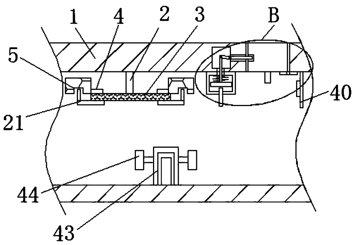
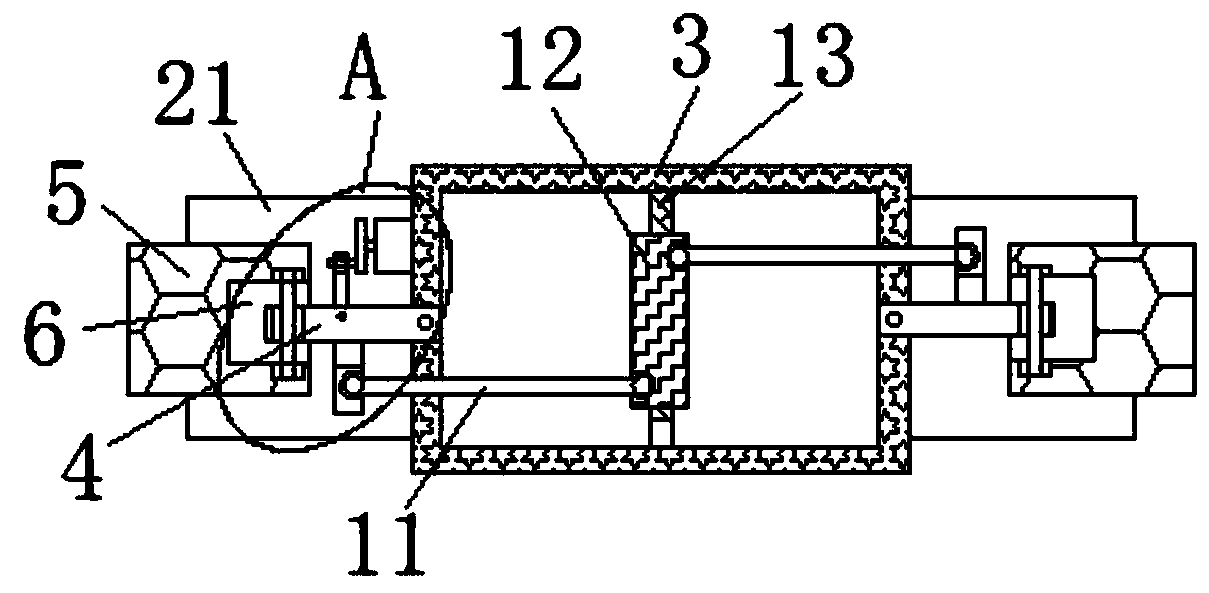
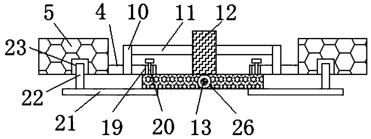
[0027] refer to Figure 1-6 , an intelligent monitoring and alarm device for an urban comprehensive pipe gallery, comprising a pipe gallery 1, an installation rod 2 is fixedly installed on the inner wall of the top side of the pipe gallery 1, an installation frame 3 is fixedly installed on the bottom end of the installation rod 2, and the installation frame 3 The top side is rotatably equipped with two rotating rods 4, and the ends of the two rotating rods 4 that are far away from each other are rotated and installed with an anti-theft alarm camera 5, and the sides where the two anti-theft alarm cameras 5 are close to each other are provided with mounting grooves 6, a...


PUM


Abstract

The invention relates to the city utility tunnel technical field, and discloses a city utility tunnel intelligent monitoring and alarm device comprising a tunnel; a mount rod is fixedly arranged on the top inner wall of the tunnel; a mount frame is fixedly arranged on the bottom of the mount rod; two rotary rods are arranged on the top side of the mount frame in a rotary mode; one end, far away from each other, of the two rotary rods are respectively provided with an anti-theft alarm camera in a rotary mode; one sides, mutually close to each other, of the two anti-theft alarm cameras are respectively provided with a mount slot. The city utility tunnel intelligent monitoring and alarm device is simple in structure; a drive rod can rotate in one cycle to enable the two rotary rods to respectively drive the two anti-theft alarm cameras to swing back and forth for one time; in addition, the anti-theft alarm camera can swing on an arc-shaped block so as to move up and down, thus realizing omnibearing monitoring, and providing the anti-theft alarm function; in addition, when the tunnel is caught in fire and electric devices fail, a cover plate can be timely opened so as to prevent the temperature from rising further higher, thus allowing maintenance people to enter the tunnel and maintain.

Description

technical field [0001] The invention relates to the technical field of urban comprehensive pipe gallery, in particular to an intelligent monitoring and alarm device for urban comprehensive pipe gallery. Background technique [0002] Urban comprehensive pipe corridor refers to the construction of a tunnel space underground in the city, integrating various engineering pipelines such as power, communication, heat, and water supply. The infrastructure and "lifeline" have a construction history of more than 50 years in China, and are still in the pilot stage. [0003] The publication number is CN106097642A, which discloses an intelligent monitoring and alarm device for urban comprehensive utility corridors, including an environment and equipment monitoring subsystem, a security subsystem, a communication subsystem, an early warning and alarm subsystem, a geographic information subsystem, and a unified management information platform 1. The pipeline temperature real-time monitori...

Claims


Application Information

Patent Timeline
Patent Type & Authority Applications(China)
IPC IPC(8): H04N7/18G08B13/196H05K7/20
CPCG08B13/19617G08B13/1963G08B13/19632H04N7/181H05K7/20136
Inventor 不公告发明人
Owner 新疆华邦智通信息科技有限公司
Why Eureka
Try Eureka