
Power supply apparatus

A power supply device and power supply technology, which is applied to circuit devices, emergency power supply arrangements, electrical components, etc., can solve the problems of high hardware cost and complicated circuit design, and achieve the effect of low circuit complexity and hardware cost

Inactive Publication Date: 2019-01-29
LITE ON TECH CORP
View PDF4 Cites 2 Cited by
  • Summary
  • Abstract
  • Description
  • Claims
  • Application Information

AI Technical Summary

Benefits of technology

The inventor proposes that it should have two circuits: one for AC signals (AC) while another for DC signals. This design allows for simpler and less expensive components than existing designs without sacrificing their functionality or performance.

Problems solved by technology

This patented technical solution described for improving the performance and efficiency of an electronics system's power supply unit involves adding two inputs: either manual or auto-switching mode, allowing it to quickly switch between different modes based on any changes made during normal operations without causing potential equipment malfunctions.

Method used


Image

  • Power supply apparatus
  • Power supply apparatus
  • Power supply apparatus

Examples


Embodiment Construction

[0048] In order to make the content of the present invention more comprehensible, the following specific embodiments are taken as examples in which the present invention can be implemented. In addition, wherever possible, elements / members / steps with the same reference numerals are used in the drawings and embodiments to represent the same or similar parts.

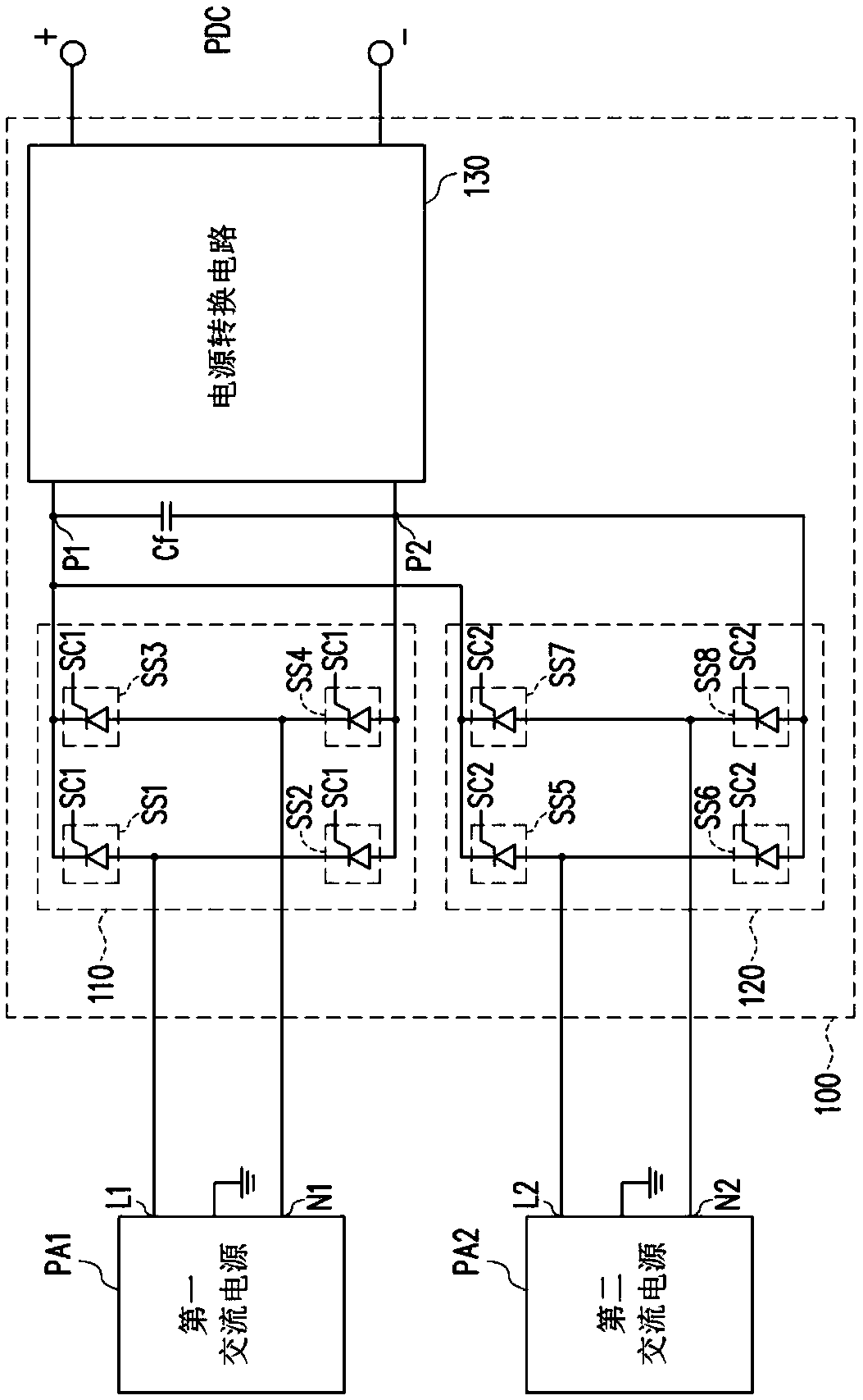
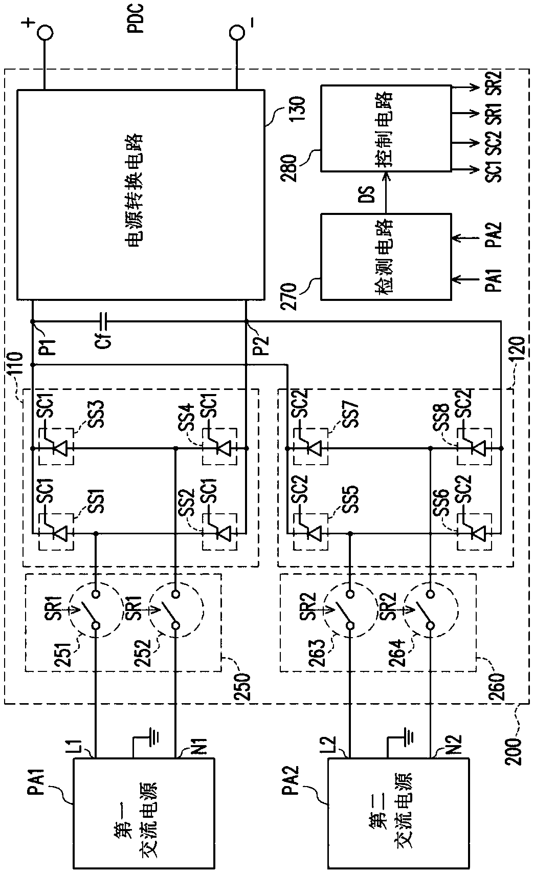
[0049] Please refer to the following figure 1 , figure 1 is a schematic circuit diagram of a power supply device 100 according to an embodiment of the present invention. Such as figure 1 As shown, the power supply device 100 may include a first rectification switch circuit 110 , a second rectification switch circuit 120 and a power conversion circuit 130 , but the invention is not limited thereto. In other embodiments of the present invention, the power conversion circuit 130 can also be disposed outside the power supply device 100 to become an independent power conversion device, which depends on actual application or ...


PUM


Abstract

A power supply apparatus including a first rectifier switching circuit and a second rectifier switching circuit is provided. The first rectifier switching circuit is coupled between a live wire terminal and a neutral wire terminal of a first AC power and a first contact and a second contact. The second rectifier switching circuit is coupled between a live wire terminal and a neutral wire terminalof a second AC power and the first contact and the second contact. The first rectifier switching circuit performs rectification on the first AC power and thereby provides a rectified power to the first contact and the second contact when a status of the first AC power is normal. The second rectifier switching circuit performs rectification on the second AC power and thereby provides the rectifiedpower to the first contact and the second contact when the status of the first AC power is abnormal.

Description


Claims


Application Information

Patent Timeline
Owner LITE ON TECH CORP
Learn More