Crankcase ventilation system and automobile

A crankcase ventilation and crankcase technology, which is applied in crankcase ventilation, machines/engines, mechanical equipment, etc., can solve the problems of long development cycle and cost, and large changes of engine parts

Active Publication Date: 2020-04-21
ZHEJIANG FENGRUI ENGINE CO LTD +1
View PDF6 Cites 0 Cited by
  • Summary
  • Abstract
  • Description
  • Claims
  • Application Information

AI Technical Summary

Problems solved by technology

[0005] The purpose of the present invention is to provide a crankcase ventilation system and an automobile to improve the implementation means of the crankcase ventilation existing in the prior art, which requires a long development period and a technical problem of cost due to a large change of the engine body.

Method used


Image

  • Crankcase ventilation system and automobile
  • Crankcase ventilation system and automobile
  • Crankcase ventilation system and automobile

Examples


Embodiment Construction

[0024] The technical solutions of the present invention will be clearly and completely described below in conjunction with the accompanying drawings. Apparently, the described embodiments are some of the embodiments of the present invention, but not all of them. Based on the embodiments of the present invention, all other embodiments obtained by persons of ordinary skill in the art without making creative efforts belong to the protection scope of the present invention.

[0025] In the description of the present invention, it should be noted that if the terms "center", "upper", "lower", "left", "right", "vertical", "horizontal", "inner", "outer" appear ", etc., the indicated orientation or positional relationship is based on the orientation or positional relationship shown in the drawings, which is only for the convenience of describing the present invention and simplifying the description, rather than indicating or implying that the referred device or element must have a specif...


PUM


Abstract

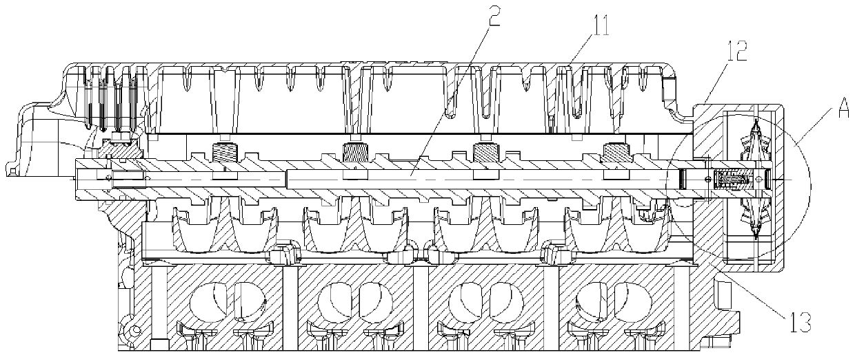
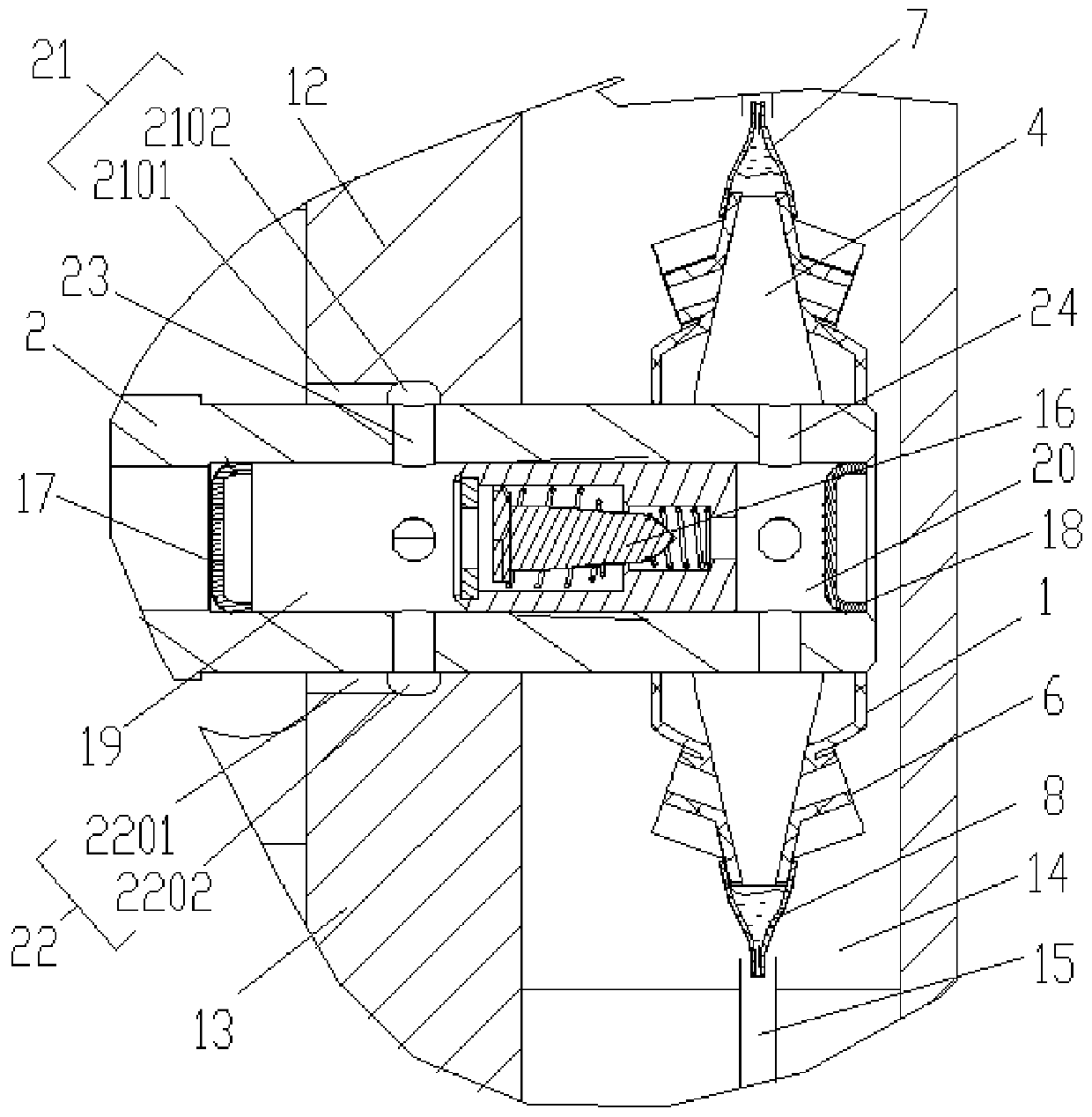
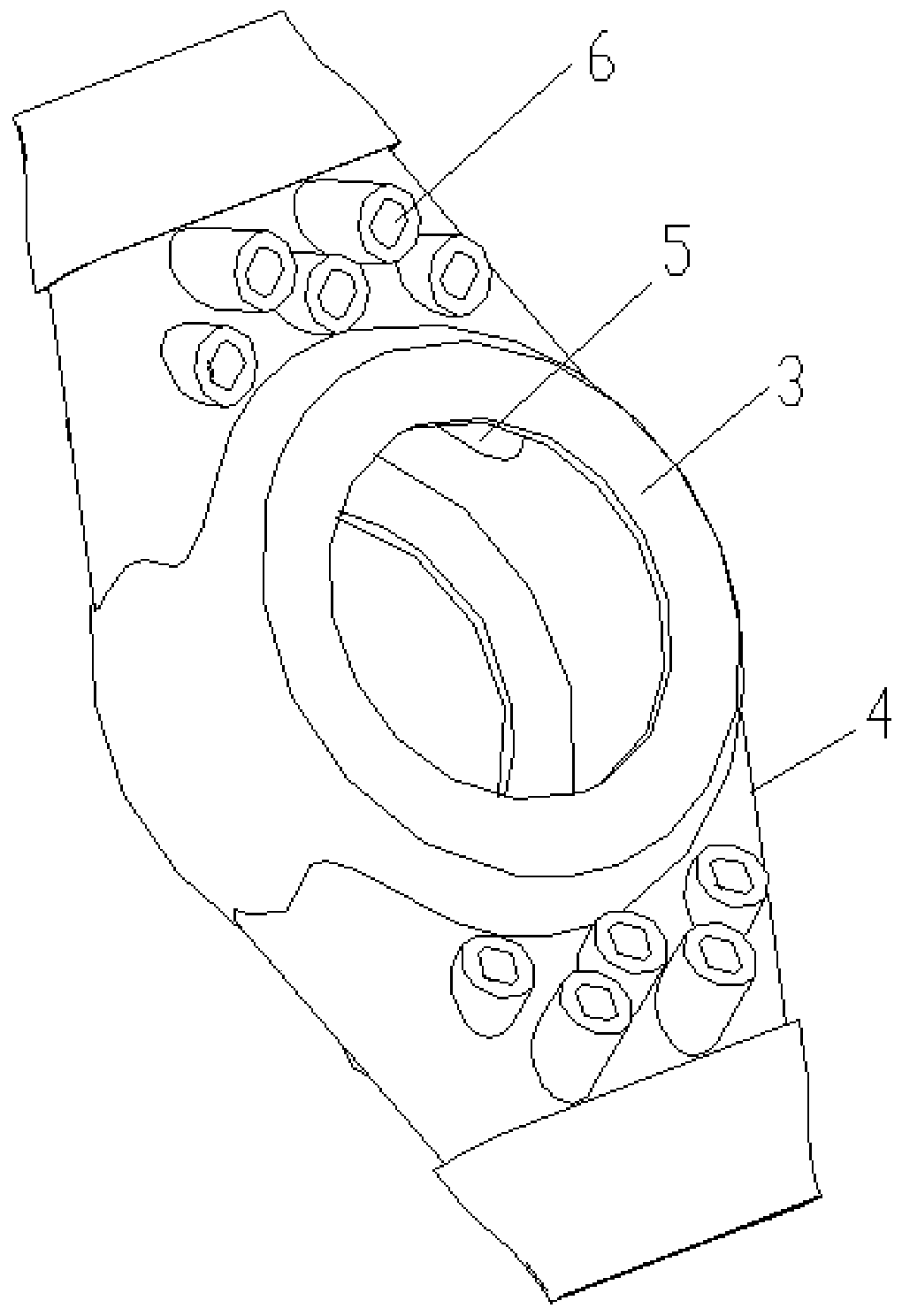
The invention provides a crankcase ventilation system and a car, and relates to the technical field of cars. The crankcase ventilation system comprises an oil and gas separator and a camshaft, the oiland gas separator is arranged in the radial direction of the camshaft, the oil and gas separator is fixedly connected with the camshaft, and the oil and gas separator is a centrifugal type oil and gas separator. In the use process, the camshaft rotates, the oil and gas separator is driven to rotate, and the oil and gas separator rotates to separate oil drops from gas. From the foregoing, the crankcase ventilation system can use rotation of the camshaft to drive the centrifugal type oil and gas separator to rotate, and separation of the oil drops and the gas is finished. The situation that theoil and gas separator is independently arranged on the crankcase is avoided, changing of an engine body part is small, and the short development period and the low cost are needed.

Description

technical field [0001] The invention relates to the technical field of automobiles, in particular to a crankcase ventilation system and an automobile. Background technique [0002] When the engine is working, the high-pressure combustible mixture and burned gas in the combustion chamber will more or less leak into the crankcase through the gap between the piston group and the cylinder, causing blow-by. The components of blow-by gas are unburned fuel gas, water vapor and exhaust gas, etc., which will dilute the engine oil, reduce the performance of the engine oil, and accelerate the oxidation and deterioration of the engine oil. Moisture condenses in the engine oil, which will form sludge and block the oil circuit; the acid gas in the exhaust gas will be mixed into the lubrication system, which will cause corrosion and accelerated wear of engine parts; blow-by gas will also cause the pressure of the crankcase to be too high and damage the crankcase. Sealed to allow oil to le...

Claims


Application Information

Patent Timeline
Patent Type & Authority Patents(China)
IPC IPC(8): F01M13/04F01M13/00
CPCF01M13/00F01M13/0011F01M13/04F01M2013/0422
Inventor 喻忠成刘岩杨万里王瑞平
Owner ZHEJIANG FENGRUI ENGINE CO LTD
Why Eureka
Try Eureka