Buffering rib of rotary drum screen and rotary drum screening machine
A technology of drum screening machine and buffer ribs, which is applied in the direction of filter screen, solid separation, grille, etc., can solve the problems of small working area of screen drum, low material screening amount, high production cost, etc., so as to improve mixing effect and prolong Stirring time and the effect of small shear resistance
- Summary
- Abstract
- Description
- Claims
- Application Information
AI Technical Summary
Problems solved by technology
Method used
Image
Examples
Embodiment 1
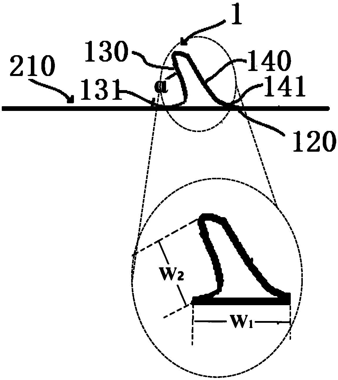
[0048] Buffer rib 1 in the present embodiment, as figure 1 As shown, the first side wall 130 faces the feed end 220 of the screen, and forms a certain angle α with the inner side wall 210 of the screen, and the included angle α is 0°.
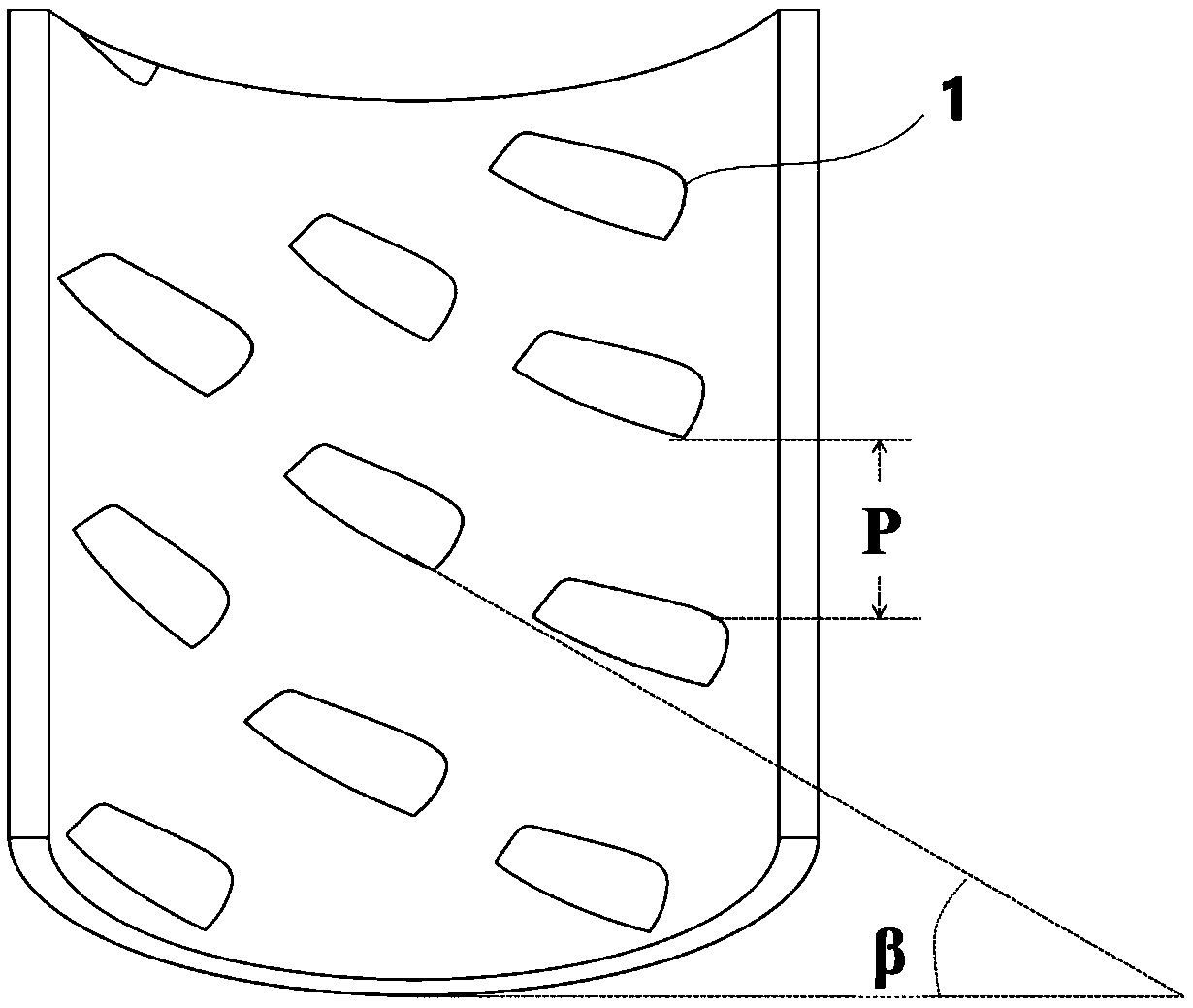
[0049] Such as image 3 As shown, the buffer ribs 1 are evenly distributed on the inner wall 210 of the screen, distributed along the inner wall 210 of the screen in a circumferential spiral shape, and arranged in a crosswise dislocation along the inner wall 210 of the screen.
[0050] The working principle of the drum screen buffer rib described in this embodiment in the drum screening machine is as follows:
Embodiment 2
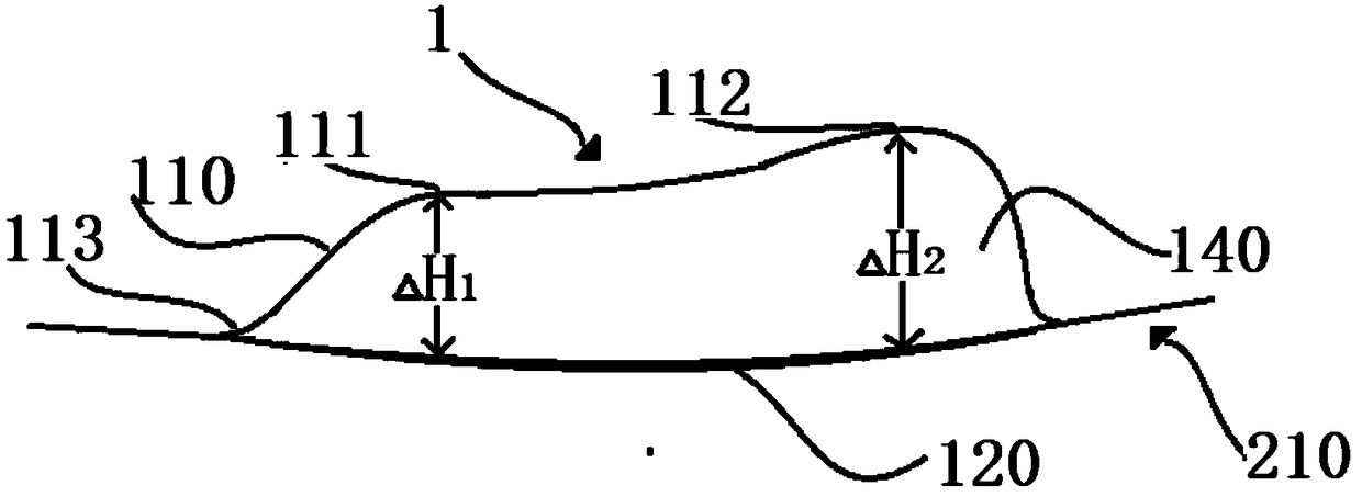
[0052] Further, compared with embodiment 1, the improvement in this embodiment lies in: combining figure 2 as well as image 3 , the front end 111 and the bottom (120) of the buffer rib towards the screen feeding end 220 have a relative height - ΔH 1 , the rear end 112 and the bottom 120 of the buffer rib towards the discharge end 230 of the screen have a relative height of two ΔH 2 , ΔH 1 less than ΔH 2 ;
[0053] The angle α formed by the first side wall 130 and the inner side wall 210 of the screen is preferably 30°.
[0054] The drum screening machine with the above-mentioned buffer ribs 1 welded on the inner wall 210 of the screen, the inner wall of the screen 2 is also coated with a layer of ultra-high molecular polyethylene membrane, the molecular weight is higher than 3 million; and the low end; the screen feed end 220 is located at the high end and is connected to the feed port 420; the screen discharge end 230 is located at the low end and is connected to the c...
Embodiment 3
[0056] Further, compared with Embodiment 2, the improvement in this embodiment lies in that the included angle α formed by the first side wall 130 of the buffer rib 1 and the inner side wall 210 of the screen is preferably 45°.
[0057] The length of the buffer rib 1 is one-tenth of the circumference of the screen 2, and the relative height between the rear end 112 and the bottom 120 is ΔH 2 One-tenth of the diameter of the screen 2.
[0058] combine image 3 The distribution pitch P of the buffer ribs 1 on the inner wall 210 of the screen is 200 mm, and the helix angle β is greater than 0° and less than 90°, preferably 10° in this embodiment.
[0059] The above-mentioned buffer ribs 1 are detachably installed on the inner side wall 210 of the screen of the drum screening machine in this embodiment, and the installation method is as follows Figure 4 Shown, mounted with bolts.
PUM
 Abstract
Description
Claims
Application Information
 - R&D Engineer
- R&D Manager
- IP Professional
- Industry Leading Data Capabilities
- Powerful AI technology
- Patent DNA Extraction
Browse by: Latest US Patents, China's latest patents, Technical Efficacy Thesaurus, Application Domain, Technology Topic, Popular Technical Reports.
© 2024 PatSnap. All rights reserved.Legal|Privacy policy|Modern Slavery Act Transparency Statement|Sitemap|About US| Contact US: help@patsnap.com


