A structure and design method of a double three-hole vertical Hall device

A vertical Hall and device structure technology, applied in the direction of Hall effect devices, electric solid state devices, semiconductor devices, etc., can solve the problems of large initial imbalance, asymmetric current flow path, and difficulty in quantifying and determining the overall influence of the device, achieving Effects of reducing initial offset, avoiding short-circuit effects, and optimizing distribution

Pending Publication Date: 2019-01-25
FUZHOU UNIV
View PDF0 Cites 0 Cited by
  • Summary
  • Abstract
  • Description
  • Claims
  • Application Information

AI Technical Summary

Problems solved by technology

The five-hole structure is symmetrical, and the initial offset is low. However, when the rotating current method is used, a large offset voltage will be generated in the remaining phases, which will affect the signal processing at the back end.
When this structure is used in the rotating current method, the current flow path is symmetrical in different phases, which can reduce the offset voltage at this time, but in each phase, its own current flow path is asymmetrical, so the initial offset is large
In order to reduce the initial imbalance, a six-hole structure appeared, that is, two contact electrodes were prepared on the outside of the four-hole structure and short-circuited, and part of the bias current would flow through them, thereby adjusting the two Hall electrodes. Voltage, but the position and size of these two contact electrodes and their impact on the overall device are difficult to quantify and determine, which increases the difficulty of the research and development process. At the same time, the current flow path of the structure itself is asymmetrical, and there is also the problem of large initial imbalance.

Method used


Image

  • A structure and design method of a double three-hole vertical Hall device
  • A structure and design method of a double three-hole vertical Hall device
  • A structure and design method of a double three-hole vertical Hall device

Examples


Embodiment Construction

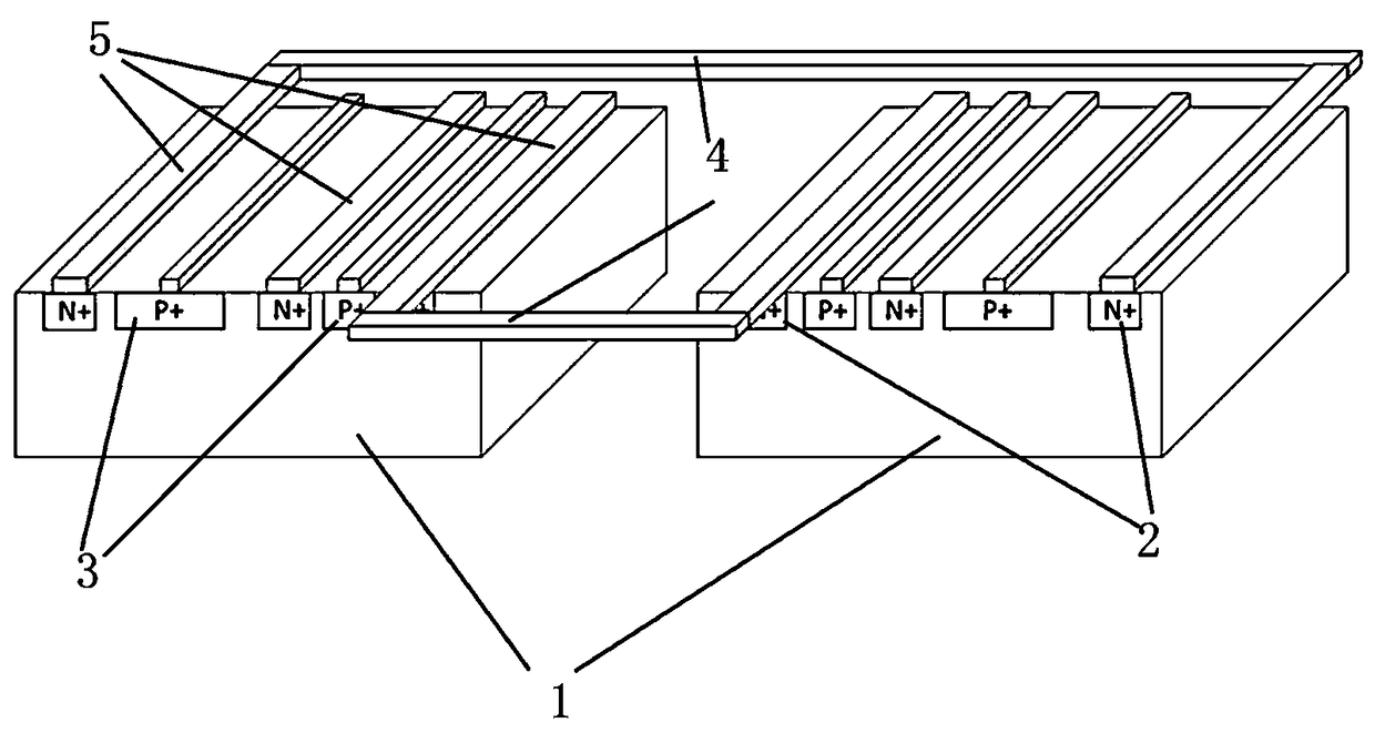
[0039] Such as Figure 1-5As shown, a double-three-hole vertical Hall device structure, the Hall device structure forms an axisymmetric structure with two identical three-hole vertical Hall devices 1 arranged side by side; There is an isolation structure between them; the N wells of the two three-hole vertical Hall devices are independent of each other and are located on the same level; the N wells are provided with three N+ regions 2 arranged in parallel in order to form a three-hole structure, and the three N+ regions Both are connected with contact electrodes 5; two three-hole vertical Hall devices are connected with contact electrodes at their edges via wires 4 to form an assembly.

[0040] The N+ is in the shape of a rectangular strip; on the N well of each three-hole vertical Hall device, the widths of the separation regions used to separate adjacent N+ regions are not equal.

[0041] A P+ region 3 is provided at each separation region; the P+ region is used to neutrali...


PUM


Abstract

The invention provides a double three-hole vertical Hall device structure and a design method thereof. The Hall device structure forms an axisymmetric structure with two identical three-hole verticalHall devices arranged side by side. An isolation structure is arranged between the left and right three-hole vertical Hall devices; The N-wells of two three-hole vertical Hall devices are independentof each other and lie in the same horizontal plane. Three N + regions arranged in parallel order are arranged on the N well to form a three-hole structure, and the three N + regions are all connectedwith contact electrodes; Two three-hole vertical Hall devices are connected with the contact electrodes at the edges of the two three-hole vertical Hall devices through wires to form an assembly; Theinvention forms a symmetrical structure by using two three-hole structures which are mirror images of each other, The symmetrical current paths in the four states are advantageous to reduce the offsetvoltage by using rotating circuits, and the contact electrodes are designed with unequal spacing. The P + region is arranged between the contact electrodes to optimize the distribution of carriers and avoid short circuit effect. The device is fabricated with high voltage process so as to have a deep N well to improve the sensitivity of the device.

Description

technical field [0001] The invention relates to the technical field of electronic components, in particular to a double-three-hole vertical Hall device structure and a design method. Background technique [0002] At present, the vertical Hall device mainly adopts a five-hole structure design, that is, five N+ regions and their corresponding contact electrodes are prepared on the N well, including a set of bias electrodes and a set of Hall electrodes. In the case of applying a bias voltage and a magnetic field, the Hall voltage is output from the two Hall electrodes. The five-hole structure is symmetrical, and the initial offset is low. However, when the rotating current method is used, a large offset voltage will be generated in the remaining phases, which will affect the signal processing at the back end. Based on the five-hole structure, by removing one of the contact electrodes, a four-hole structure emerged. When this structure is used in the rotating current method, t...

Claims


Application Information

Patent Timeline
Patent Type & Authority Applications(China)
IPC IPC(8): H01L43/06H01L27/22G06F17/50
CPCG06F30/30H10B61/00H10N59/00H10N52/101
Inventor 魏榕山杜宇轩刘莉莉
Owner FUZHOU UNIV
Why Eureka
Try Eureka