
Gate driving circuit and display device

A gate drive circuit and gate drive technology, applied in static indicators, instruments, etc., can solve problems such as the narrow frame design, high display uniformity requirements, and large load of the unfavorable liquid crystal display device, so as to improve the display quality. , The effect of reducing signal line load and reducing power consumption

Active Publication Date: 2019-01-25
KUSN INFOVISION OPTOELECTRONICS
View PDF12 Cites 7 Cited by
  • Summary
  • Abstract
  • Description
  • Claims
  • Application Information

AI Technical Summary

Problems solved by technology

[0005] However, for a large-sized liquid crystal display device, the load driven by the gate drive circuit is very large, and the uniformity of the display is high, which requires a large and stable gate drive circuit with a large output voltage value. signal, the existing technology generally solves the above problems by increasing the number and size of switching elements and capacitors in the gate drive circuit, but the above method is not conducive to the narrow frame design of the liquid crystal display device, and consumes a lot of power

Method used

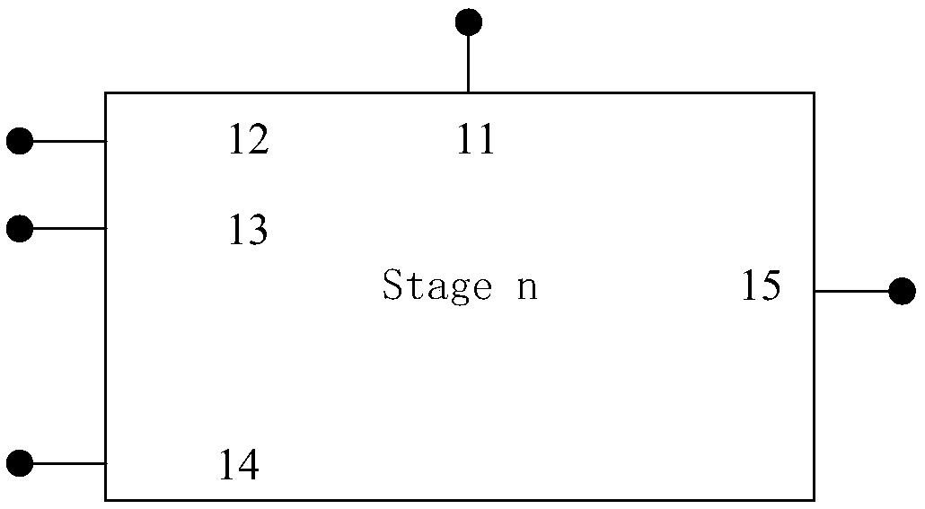
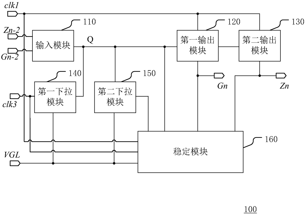
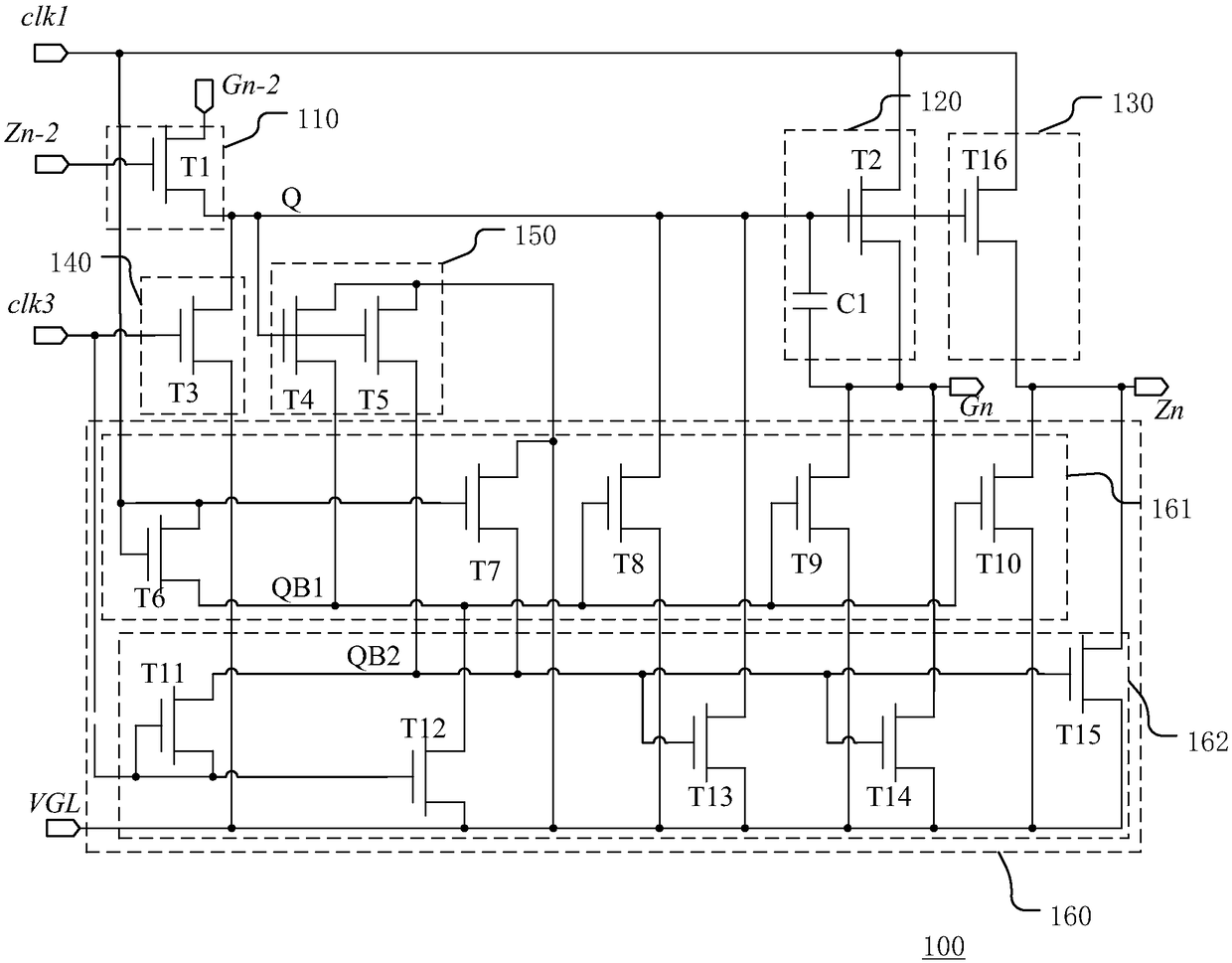

Image

  • Gate driving circuit and display device
  • Gate driving circuit and display device
  • Gate driving circuit and display device

Examples


Embodiment Construction

[0039] The present invention will be described in more detail below with reference to the accompanying drawings. In the various figures, like elements are designated by like reference numerals. For the sake of clarity, various parts in the figures have not been drawn to scale. Additionally, some well-known parts may not be shown in the drawings.

[0040] Numerous specific details of the invention are described below, such as the construction of components, materials, dimensions, processing and techniques, in order to provide a clearer understanding of the invention. However, as can be understood by one skilled in the art, the present invention may be practiced without these specific details.

[0041] The gate driving circuit (also referred to as a shift register) of the present invention includes a multi-level gate driving unit (also referred to as a shift register unit), and each level of the gate driving unit is respectively connected with each row of gate lines on the dis...


PUM


Abstract

The invention discloses a gate driving circuit, comprising a plurality of gate driving units in cascade, characterized in that the plurality of gate driving units respectively comprise an input moduleconnected with a first node and charging the first node according to a first start signal and a second start signal; a first output module connected to the input module at the first node, generatinga gate driving signal of the present stage according to the first clock signal, and providing the gate driving signal of the present stage at the output terminal; the second output module is connectedwith the input module to the first node, and generates a transfer signal of the current stage according to the first clock signal; a first pull-down module the pulls down the first node to the low level signal under the control of the second clock signal; and a stabilizing module which maintains the gate signal of the current stage at a low level under the control of the first clock signal and the second clock signal. The gate driving circuit can realize a narrow frame and a low power consumption display device, and reduce the occurrence of the cross ripple phenomenon.

Description

technical field [0001] The present invention relates to the field of display technology, and more particularly to a gate driving circuit and a display device. Background technique [0002] The liquid crystal display device is a display device that changes the light transmittance of the light source by using the phenomenon that the arrangement direction of the liquid crystal molecules changes under the action of an electric field. Due to the advantages of good display quality, small size and low power consumption, liquid crystal display devices have been widely used in mobile terminals such as mobile phones and large-sized display panels such as flat-panel TVs. Most of the liquid crystal displays on the current market are projection type liquid crystal displays, which include a liquid crystal panel and a backlight module. The working principle of the liquid crystal panel is to place liquid crystal molecules in the middle of two parallel glass substrates, and apply a driving ...

Claims


Application Information

Patent Timeline
IPC IPC(8): G09G3/36
CPCG09G3/3677
Inventor 柯中乔张鼎郭文豪段周雄
Owner KUSN INFOVISION OPTOELECTRONICS
Learn More