
A Mobile Power Sharing System

A mobile power supply and sharing system technology, applied in the direction of current collectors, electric vehicles, electrical components, etc., can solve the problems of heavy mobile power and the need for frequent charging, and achieve the effect of facilitating life, improving convenience, and improving use efficiency

Inactive Publication Date: 2019-01-22
上海善解人意信息科技有限公司
View PDF6 Cites 2 Cited by
  • Summary
  • Abstract
  • Description
  • Claims
  • Application Information

AI Technical Summary

Problems solved by technology

However, mobile power is usually heavy and needs to be charged frequently. A considerable number of people do not carry mobile power with them every day. When electronic devices (especially mobile phones) are low on power, they will cause great trouble.

Method used


Image

  • A Mobile Power Sharing System
  • A Mobile Power Sharing System
  • A Mobile Power Sharing System

Examples


Embodiment 1

[0031] see figure 1 , the present invention discloses a mobile power sharing system, the mobile power sharing system includes: several mobile power sources 3, several mobile power locking terminals 2, and a server 1; the server 1 is respectively connected to each mobile power locking terminal 2, each mobile power source 3 .

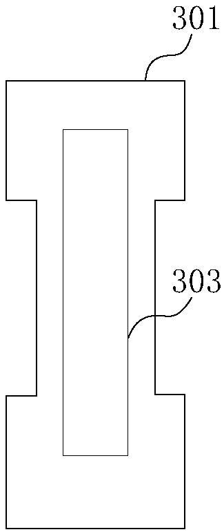
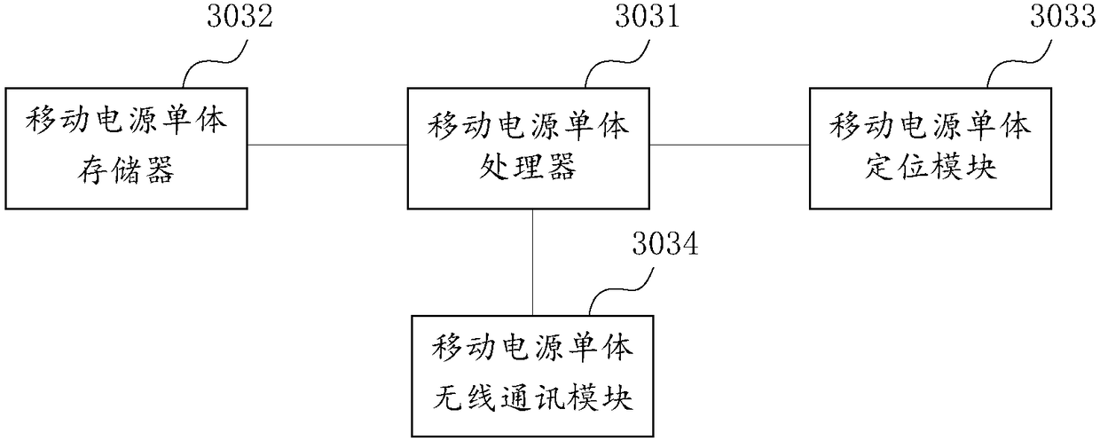
[0032] see figure 2 Each mobile power supply 3 includes a mobile power supply body 301 printed with a unique identification code, a mobile power supply single circuit board 303 arranged in the mobile power supply main body 301; see image 3 , the mobile power unit circuit board 303 includes a mobile power unit processor 3031, a mobile power unit memory 3032, a mobile power unit positioning module 3033, a mobile power unit wireless communication module 3034, and a mobile power unit processor 3031 The mobile power unit memory 3032, the mobile power unit positioning module 3033, and the mobile power unit wireless communication module 3034 are respectivel...

Embodiment 2

[0044] The difference between this embodiment and Embodiment 1 is that in this embodiment, the locking terminal power module includes a solar panel, a rechargeable battery, and a charging control circuit, and the rechargeable battery is connected to the solar panel and the charging control circuit respectively.

Embodiment 3

[0046] The difference between this embodiment and Embodiment 1 is that in this embodiment, the locking terminal power module includes a hydrogen storage container, a hydrogen fuel cell, and a charging control circuit. The hydrogen fuel cell uses the hydrogen stored in the hydrogen storage container to generate electricity, and the hydrogen fuel cell The battery is connected to the charging control circuit.


PUM


Abstract

The invention discloses a mobile power sharing system, comprising a plurality of mobile power sources, a plurality of mobile power source locking terminals and a server. Each mobile power source includes a mobile power source body provided with a representative unique identification code and a single control circuit board arranged on the mobile power source body. At least one lock position is arranged at each movable power supply locking terminal, that movable power supply can be locked in the loc position, and each locking position is provided with a locking mechanism; The locking mechanism comprises an electric unlocking assembly or an electromagnetic unlocking assembly; The mobile power supply locking terminal is provided with a locking terminal control circuit, a locking terminal wireless communication module and a locking terminal power supply module. The mobile power sharing system provided by the invention can realize the sharing and use of the mobile power, greatly facilitatespeople's life, does not have to worry about being unable to charge outside, and effectively improves the use efficiency of the mobile power.

Description

technical field [0001] The invention belongs to the technical field of daily necessities, and relates to a mobile power supply, in particular to a mobile power supply sharing system. Background technique [0002] Mobile Power Pack (MPP), also known as power bank, travel charger, etc., is a portable charger that integrates power supply and charging functions, and can charge digital devices such as mobile phones and tablets anytime, anywhere. Generally, lithium batteries (or dry batteries, less common) are used as power storage units, which are convenient and quick to use. [0003] Nowadays, with the widespread popularity of electronic devices (such as mobile phones, cameras, and tablet computers), the difficulty of charging has become the main factor restricting the use of electronic devices at will. Subsequently, the appearance of mobile power supply effectively prolongs the use time of electronic equipment. However, mobile power supplies are usually heavy and need to be r...

Claims


Application Information

Patent Timeline
Patent Type & Authority Applications(China)
IPC IPC(8): H02J7/00G10L15/22E05B47/00E05B47/02G07F17/00
CPCE05B47/0012E05B47/02G07F17/00G10L15/22G10L2015/223G10L2015/225H02J7/0003H02J2207/40
Inventor 鄢琴王熙睿
Owner 上海善解人意信息科技有限公司
Learn More