
A battery module heating device and a battery module

A battery module and heating device technology, which is applied to battery/fuel cell control devices, battery pack components, secondary batteries, etc. Low efficiency and other problems, to achieve the effect of improving heat utilization, reducing occupied space, and improving energy utilization

Pending Publication Date: 2019-01-22
BEIJING PRIDE NEW ENERGY BATTERY
View PDF0 Cites 3 Cited by
  • Summary
  • Abstract
  • Description
  • Claims
  • Application Information

AI Technical Summary

Problems solved by technology

[0003] At present, the heating scheme of prismatic shell battery modules usually uses a heating sheet to heat multiple cells in a single row. The defect of this solution is that the heating sheet heats the cells on one side and does not heat the cells on the other side, so the energy utilization rate is not high.
Moreover, there is no heat-conducting medium between the heating plate and the battery cell or it is filled with a heat-conducting silica gel sheet. The actual contact area between the heating plate and the battery cell is not high, that is, the heating efficiency is not high.

Method used


Image

  • A battery module heating device and a battery module
  • A battery module heating device and a battery module
  • A battery module heating device and a battery module

Examples


Embodiment 1

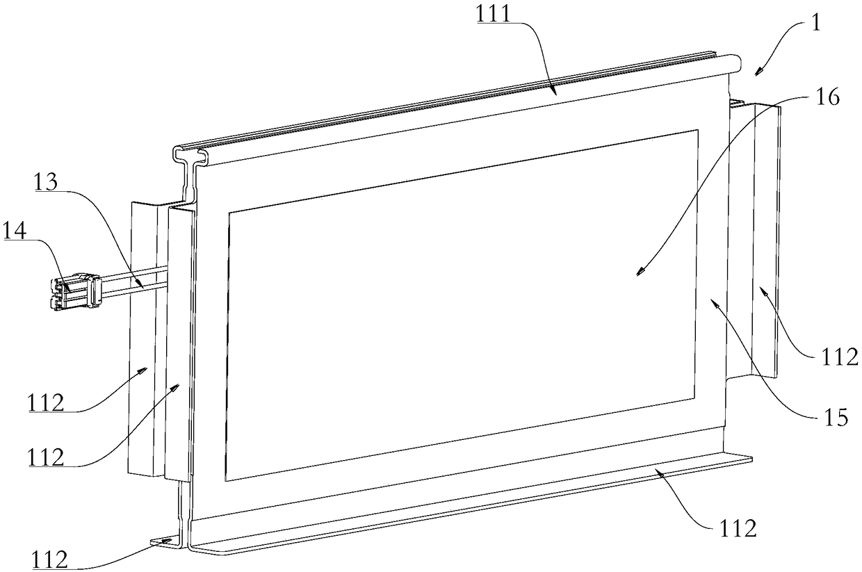
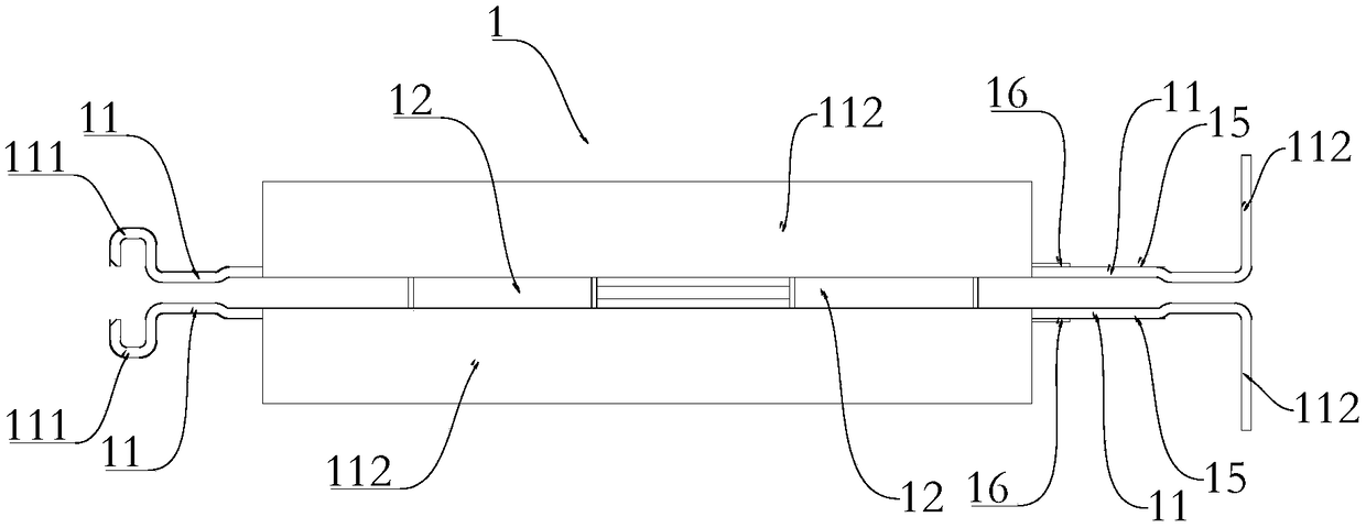
[0041] Such as figure 1 and figure 2 As shown, a heating device for a battery module in this embodiment includes two connecting plates 11 and a heating element 12, the two connecting plates 11 are arranged opposite to each other, and an installation The heating element 12 is located in the installation gap and is fixedly connected to the two connecting plates 11 respectively.

[0042] The connecting plate 11 of this embodiment is processed by a profile mold, and the material is 6 series aluminum, which has high strength and rigidity.

[0043] In the heating device of this embodiment, a heating element is arranged between the two connecting plates. When the heating device is used in a battery module, the two connecting plates can be heated respectively through the heating element, and then the heating element in contact with the connecting plates can be heated. The electric core is heated, so that the heat energy generated by the heating element can be absorbed by the electr...

Embodiment 2

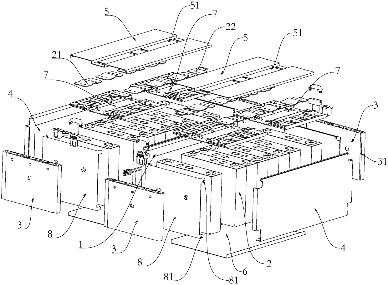
[0053] Such as image 3 As shown, a battery module in this embodiment includes a plurality of battery cells 2, a casing and the heating device, and a plurality of the battery cells 2 are arranged in multiple rows and installed in the casing, two adjacent rows The heating device 1 is installed between the battery cells 2, the side of the connecting plate 11 away from the heating element 12 is in contact with the end of a row of battery cells 2, and the connecting plate 11 is clamped with the casing .

[0054] In the battery module of this embodiment, a heating device is arranged between the two rows of cells, which can heat the two rows of cells at the same time, so that the heat of the heating device can be absorbed by the cells to the greatest extent, thereby improving the utilization rate of heat; The connecting plate is clamped with the shell, so that the heating device is installed more firmly, and the heating device is prevented from shaking in the battery module. Two r...


PUM


Abstract

The invention relates to a battery module heating device and a battery module. The heating device comprises two connecting plates and heating elements. The two connecting plates are arranged oppositeto each other. A mounting gap is reserved between the two connecting plates. The heating elements are arranged in the mounting gap and are fixedly connected with the two connecting plates respectively. The heating device of the invention, A heating element is arranged between the two connecting plates. When the heating device is used in the battery module, the two connecting plates can be heated by the heating element respectively, and the cell contacting with the connecting plate can be heated, so that the heat energy generated by the heating element can be absorbed by the cell maximally, andthe utilization rate of energy can be improved.

Description

technical field [0001] The invention relates to the technical field of new energy vehicles, in particular to a battery module heating device and a battery module. Background technique [0002] With the decline of the new energy vehicle subsidy policy, the new energy vehicle industry is facing the huge challenge of reducing product costs and increasing energy density, especially the battery system design that directly affects the subsidy amount has come to an unprecedented stage. The temperature of the battery cell itself in the battery system directly affects the service life and safety of the battery pack. When the temperature of the battery cell is lower than 0°C, it is easy to cause lithium decomposition during charging or power reduction during discharge. At this time, it is necessary to improve the battery cell itself. temperature, and under the premise of reducing cost and increasing energy density, how to improve the energy utilization rate of the heating device, redu...

Claims


Application Information

Patent Timeline
IPC IPC(8): H01M2/10H01M10/615H01M10/625B60L58/27H01M50/249
CPCH01M10/615H01M10/625H01M50/20Y02T10/70Y02E60/10
Inventor 冯志永赵孟盛力
Owner BEIJING PRIDE NEW ENERGY BATTERY
Learn More