
Bandpass filter

A band-pass filter and optical filter technology, applied in the field of optics, can solve problems such as waste and poor versatility

Inactive Publication Date: 2019-01-22
扬州市华盛光学仪器厂
View PDF0 Cites 0 Cited by
  • Summary
  • Abstract
  • Description
  • Claims
  • Application Information

AI Technical Summary

Problems solved by technology

However, the existing optical filters need to use different optical filters when observing different objects, and the existing optical filters are integrally formed with the mounting shell of the optical filter during the processing stage to form a filter lens. Users often need to replace the entire filter lens if they want to replace the filter, which causes huge waste and poor versatility

Method used


Image

  • Bandpass filter
  • Bandpass filter

Examples


Embodiment Construction

[0009] The preferred embodiments of the present invention will be described in detail below in conjunction with the accompanying drawings, so that the advantages and features of the present invention can be more easily understood by those skilled in the art, so as to define the protection scope of the present invention more clearly.

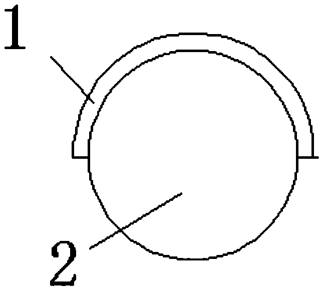
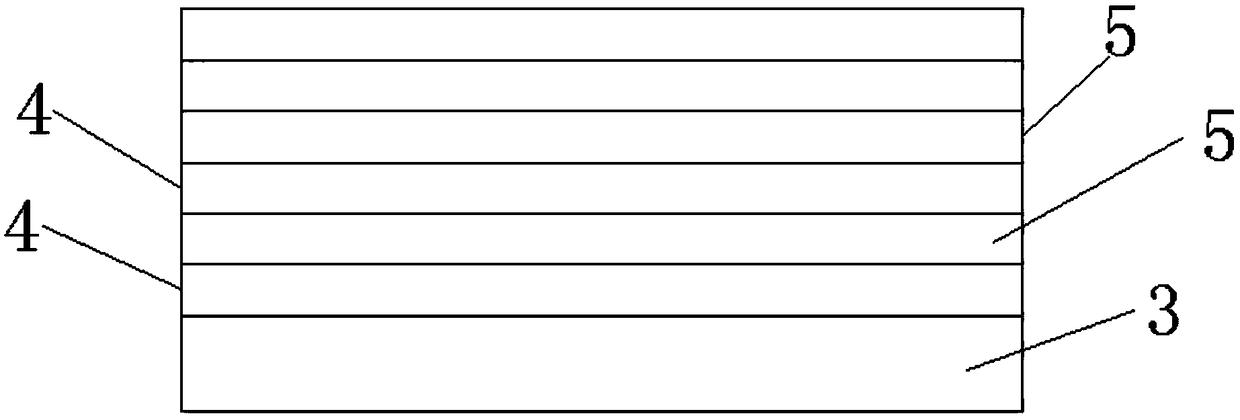
[0010] Such as figure 1 and figure 2 A bandpass filter is shown, including a mounting case and a filter assembly arranged in the mounting case, the filter assembly includes a frame 1 and a filter 2 arranged in the frame 1, and the filter is movably arranged in the frame 1 Inside, the optical filter includes a substrate 3 and TiO layers alternately arranged on the substrate from bottom to top. 2 Coating 4 and SiO 2 Coating 5, TiO 2 Coating 4 and SiO 2 The film layers 5 are arranged alternately, and the substrate 3 is HB700 colored glass.

[0011] Since the optical filter is movable in the frame, the optical filter can be replaced convenientl...


PUM


Abstract

The invention relates to a bandpass filter, comprising a mounting shell and a filtering component disposed in the mounting shell, wherein the filtering component comprises a frame and an optical filter disposed in the frame, the optical filter is disposed in the frame, the optical filter comprises a substrate, and a TiO2 film layer and an SiO2 film layer, which are alternately disposed on the substrate from bottom to top in sequence, the TiO2 film layer and the SiO2 film layer are alternately disposed, and the substrate is HB700 colored glass. After the above structure is adopted, since the optical filter is movably disposed in the frame, the optical filter can be replaced conveniently and quickly; the spectral properties of the optical filter are stable, the film layers are dense, the adhesive force is good, the film system structure is simple, and the bandpass filter is easy to implement.

Description

technical field [0001] The invention relates to the field of optical technology, in particular to a bandpass filter. Background technique [0002] A filter with cut-off regions on both sides of the transmission band of the spectral characteristic curve is called a band-pass filter. Bandpass filters are an important class of optical thin film components, which are widely used in chemistry, spectroscopy, laser, astrophysics, optical fiber communication, biology and other fields. [0003] When astronomy enthusiasts observe objects, in order to improve the accuracy of graphic spectrum observation, it is often necessary to add a filter to the front end of the observation device, so as to filter the useless interfering light. However, the existing optical filters need to use different optical filters when observing different objects, and the existing optical filters are integrally formed with the mounting shell of the optical filter during the processing stage to form a filter le...

Claims


Application Information

Patent Timeline
Patent Type & Authority Applications(China)
IPC IPC(8): G02B7/00G02B5/20
CPCG02B7/006G02B5/20
Inventor 王志涛
Owner 扬州市华盛光学仪器厂
Learn More