Automatic leveling laser transmitter fixture

A laser transmitter and flattening technology, which is applied in light guides, optics, instruments, etc., can solve problems such as difficult coupling, uneven bonding, and large changes in optical power, and achieve a large operating space, small footprint, and compact structure. Effect

Active Publication Date: 2019-01-22
CENT SOUTH UNIV
View PDF4 Cites 8 Cited by
  • Summary
  • Abstract
  • Description
  • Claims
  • Application Information

AI Technical Summary

Problems solved by technology

Due to certain processing errors in the metal parts, the upper end surface of the clamped part (the surface used for coupling and welding) is not horizontal (with a certain degree of inclination), so it will not fit flat with the upper workpiece (optical interface), resulting in Coupling is difficult and optical power changes greatly after soldering

Method used


Image

  • Automatic leveling laser transmitter fixture
  • Automatic leveling laser transmitter fixture
  • Automatic leveling laser transmitter fixture

Examples


Embodiment Construction

[0029] The specific implementation manners of the present invention will be further described below in conjunction with the drawings and examples. The following examples are only used to illustrate the technical solution of the present invention more clearly, but not to limit the protection scope of the present invention.

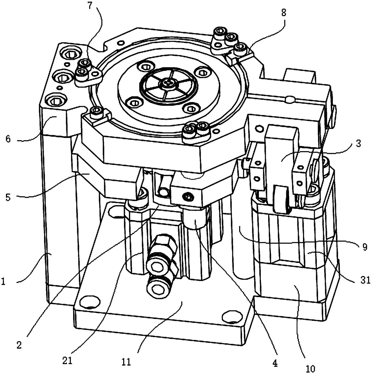
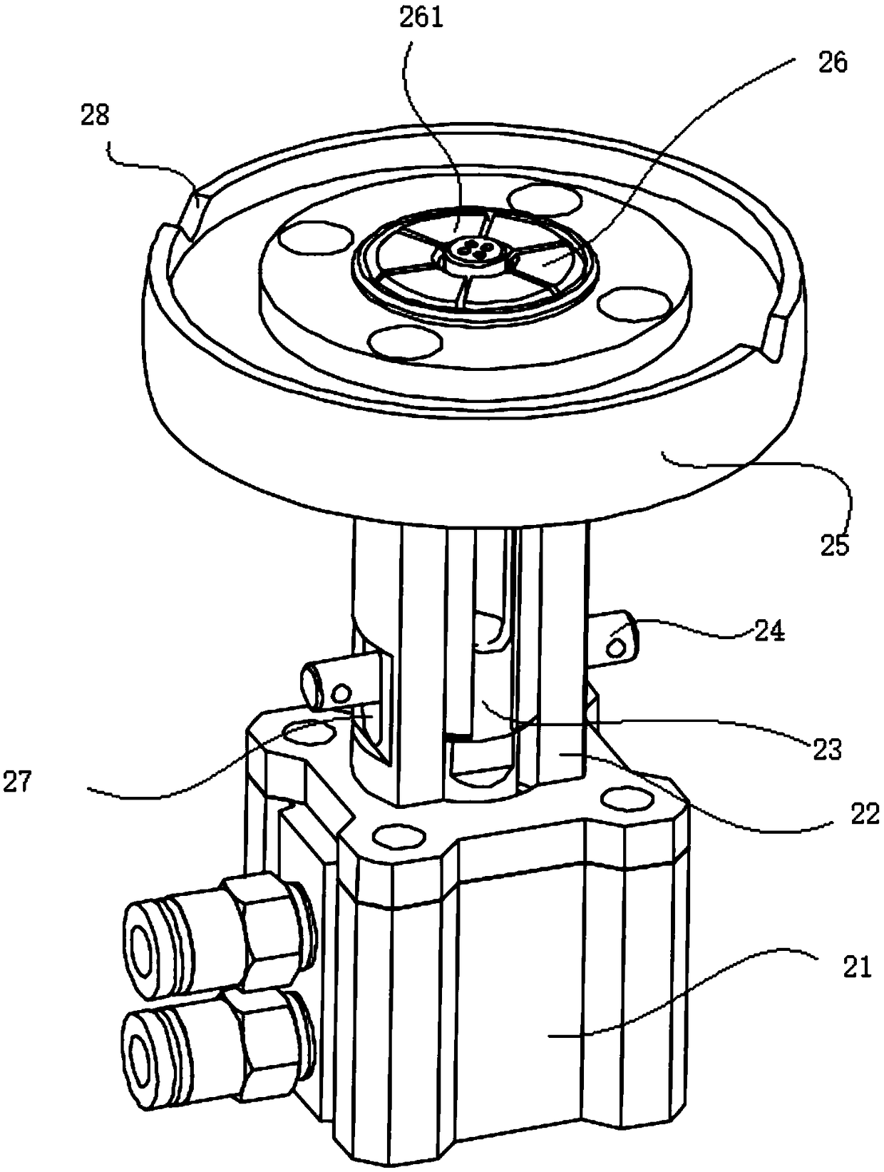
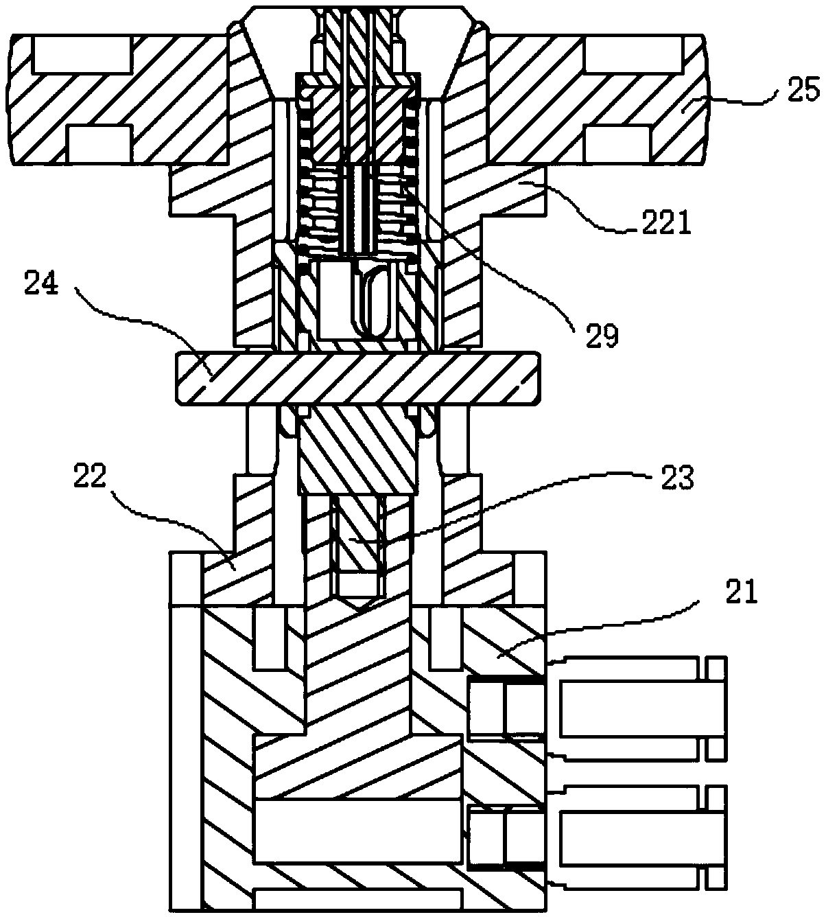
[0030] Such as Figure 1-4As shown, an automatic flattening laser transmitter fixture includes a frame, and a locking and positioning assembly arranged on the frame, a floating assembly 2, an angle fixing assembly 3, and a level adjustment assembly; the locking and positioning assembly Set on the upper part of the frame, the floating assembly 2 includes a movable disk 25 with a hole in the middle, a locking sleeve 22 that passes through the hole in the middle of the movable disk 25 and is tightly connected with the movable disk 25, and is arranged on the locking sleeve. Clamps in 22; the locking and positioning device can lock and position the floating ass...


PUM


Abstract

The invention discloses an automatic leveling laser transmitter fixture, which comprises a frame, and a locking positioning component, a floating component, an angle fixing component, and a levelnessadjusting component, which are disposed on the frame. The locking positioning component is arranged on the upper portion of the frame; the floating component comprises a movable disc with a hole in the middle, a locking sleeve which penetrates the hole in the middle of the movable disc and is tightly connected with the movable disc and a fixture which is arranged in the locking sleeve; the lockingpositioning device can lock and position the floating component; the levelness adjusting component comprises a spring plunger and a plunger support, which are arranged below the movable disc; the levelness adjusting component can adjust the levelness of the movable disc; and the angle fixing component is used for providing locking force for the locking positioning component. The fixture in the invention can better adjust the position of the laser transmitter so that an optical interface is tightly attached to the laser transmitter; the angle position can be automatically adjusted; and it canbe realized that the laser transmitter is automatically ejected after completing coupling, thereby bringing convenience for fetching.

Description

technical field [0001] The invention relates to the technical field of automatic coupling and packaging of optoelectronic devices, in particular to an automatic flattening laser transmitter fixture. Background technique [0002] With the development of optical fiber communication and optical fiber sensing technology, the preparation of optoelectronic devices has become the key to the progress of optical information technology. In optical communication products, the demand for optoelectronic devices such as TOSA—laser emitting device, BOSA—single-fiber bidirectional product (integrated sending and receiving) is increasing with the development, and its function is mainly to realize the photoelectric conversion of signals. The structural composition of optical devices is mainly laser transmitter TO (Transmitter Optical) + metal parts + optical interface. The main process of packaging and production of optoelectronic devices is to first couple and align the laser transmitter TO ...

Claims


Application Information

Patent Timeline
Patent Type & Authority Applications(China)
IPC IPC(8): G02B6/42
CPCG02B6/4245
Inventor 段吉安彭晋文于凯旋涂凯扬仲顺顺颜科舒斌戚媛婧
Owner CENT SOUTH UNIV
Why Eureka
Try Eureka