Tube-type heat exchanger for producing anhydrous hydrofluoric acid and manufatcuring method of tube-type heat exchanger

A tube-and-tube heat exchanger, anhydrous hydrofluoric acid technology, applied in the direction of heat exchanger type, heat exchanger shell, indirect heat exchanger, etc., can solve the problem of unable to clean the heat exchanger, destroy the heat Low thermal efficiency and other issues, to achieve the effect of preventing blockage and leakage, reducing noise and increasing service life

Inactive Publication Date: 2019-01-22
浙江森田新材料有限公司
View PDF6 Cites 4 Cited by
  • Summary
  • Abstract
  • Description
  • Claims
  • Application Information

AI Technical Summary

Problems solved by technology

[0003] The tube-and-tube heat exchanger is the most widely used heat exchanger in chemical and alcohol production. The structure of the tube-and-tube heat exchanger is simple, compact, and cheap. Both ends of the shell, the connection between the tube bundle and the tube sheet and the shell are rigid, and there are two fluids at different temperatures inside and outside the tubes. In order to avoid blockage of the heat exchanger, it is necessary to clean the inside of the heat exchanger frequently. Due to the traditional The tube sheet and shell of the tube-and-tube heat exchanger are welded and fixed, and the inside of the heat exchanger cannot be thoroughly cleaned. The accumulation of scale will cause problems of low heat exchange efficiency, high cost, and low benefit. At the same time, due to the different thermal expansions of the two fluids, It will generate a large temperature difference stress, which will cause the tube bundle to fall off the shell and destroy the heat exchanger

Method used


Image

  • Tube-type heat exchanger for producing anhydrous hydrofluoric acid and manufatcuring method of tube-type heat exchanger
  • Tube-type heat exchanger for producing anhydrous hydrofluoric acid and manufatcuring method of tube-type heat exchanger
  • Tube-type heat exchanger for producing anhydrous hydrofluoric acid and manufatcuring method of tube-type heat exchanger

Examples


Embodiment Construction

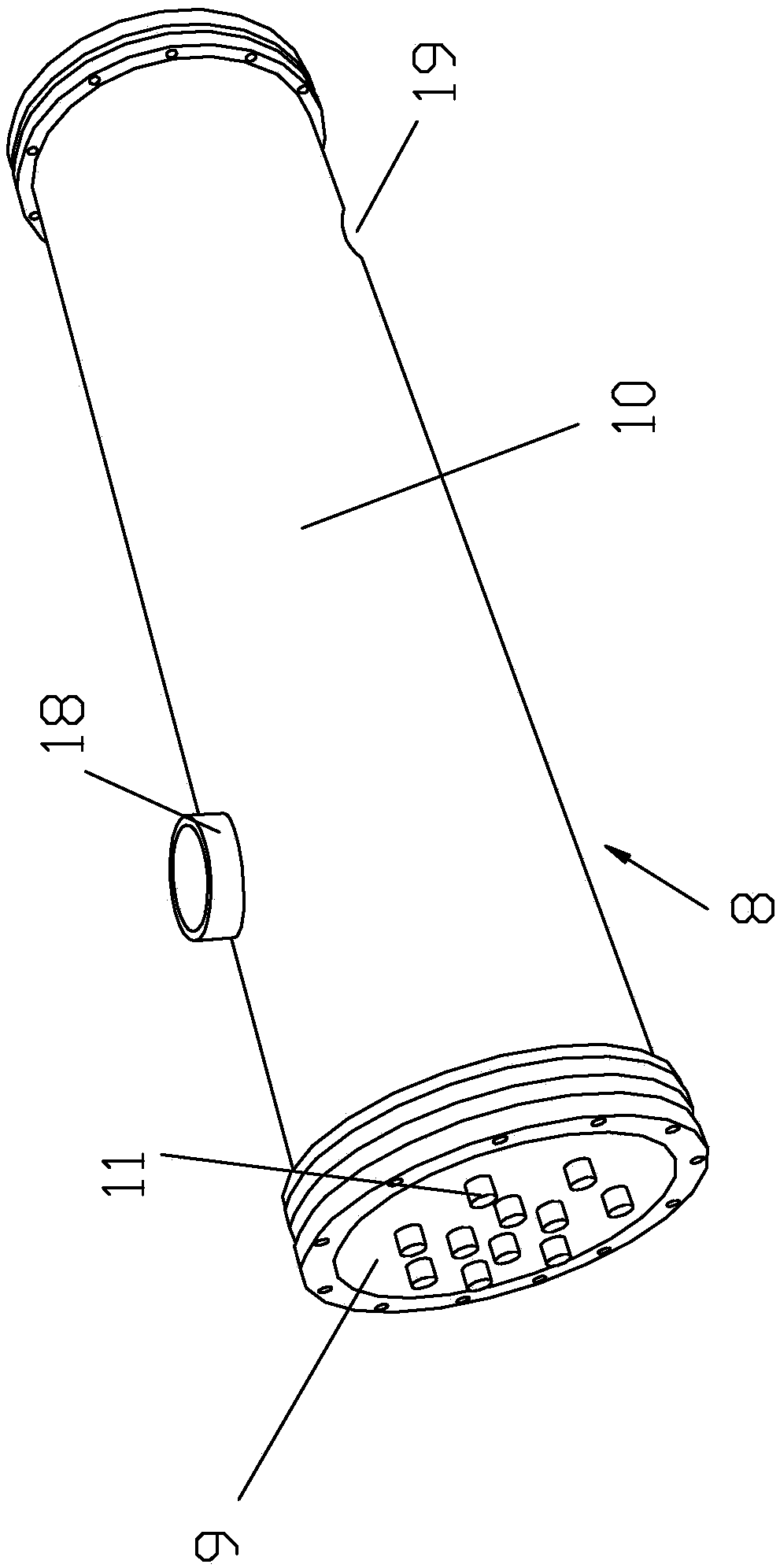
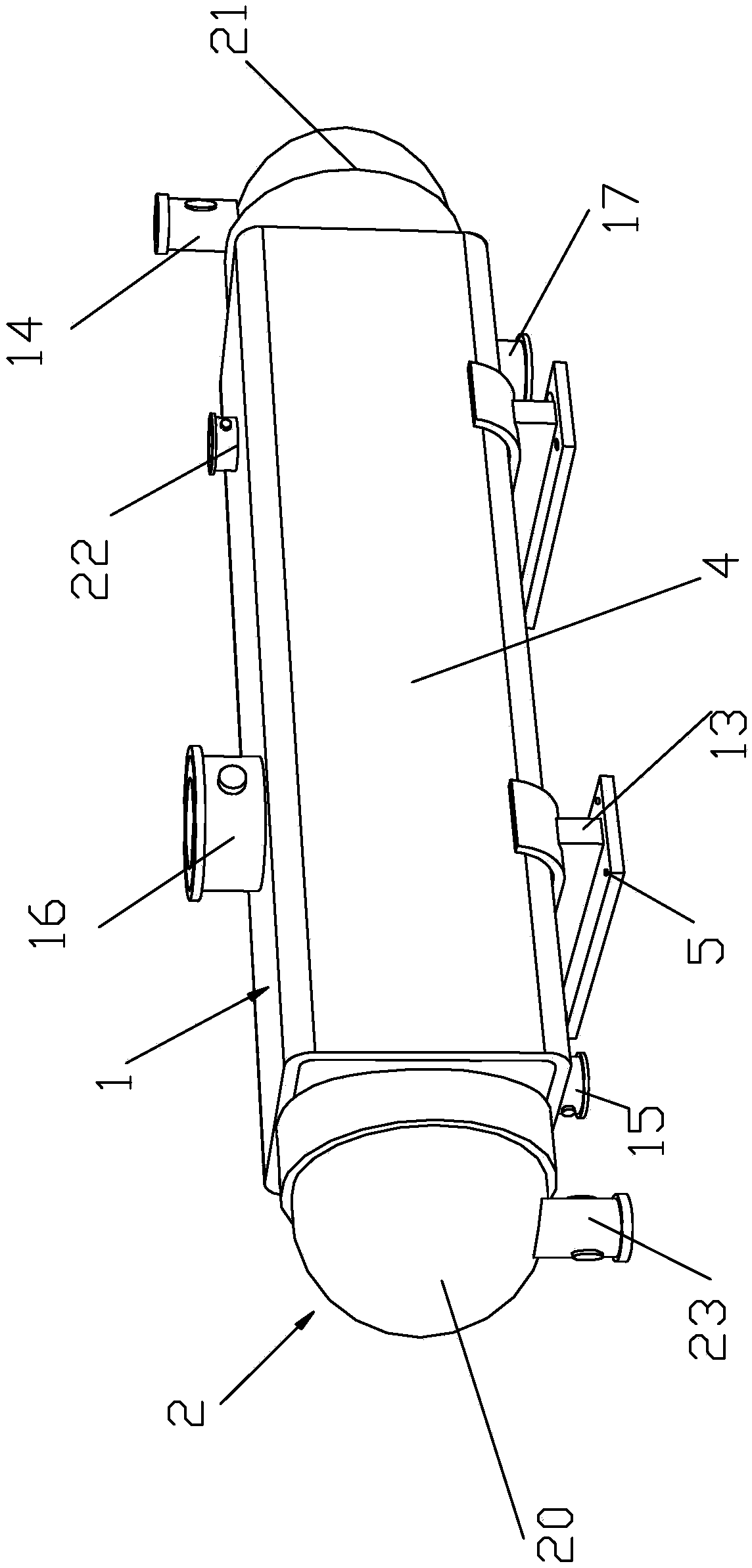
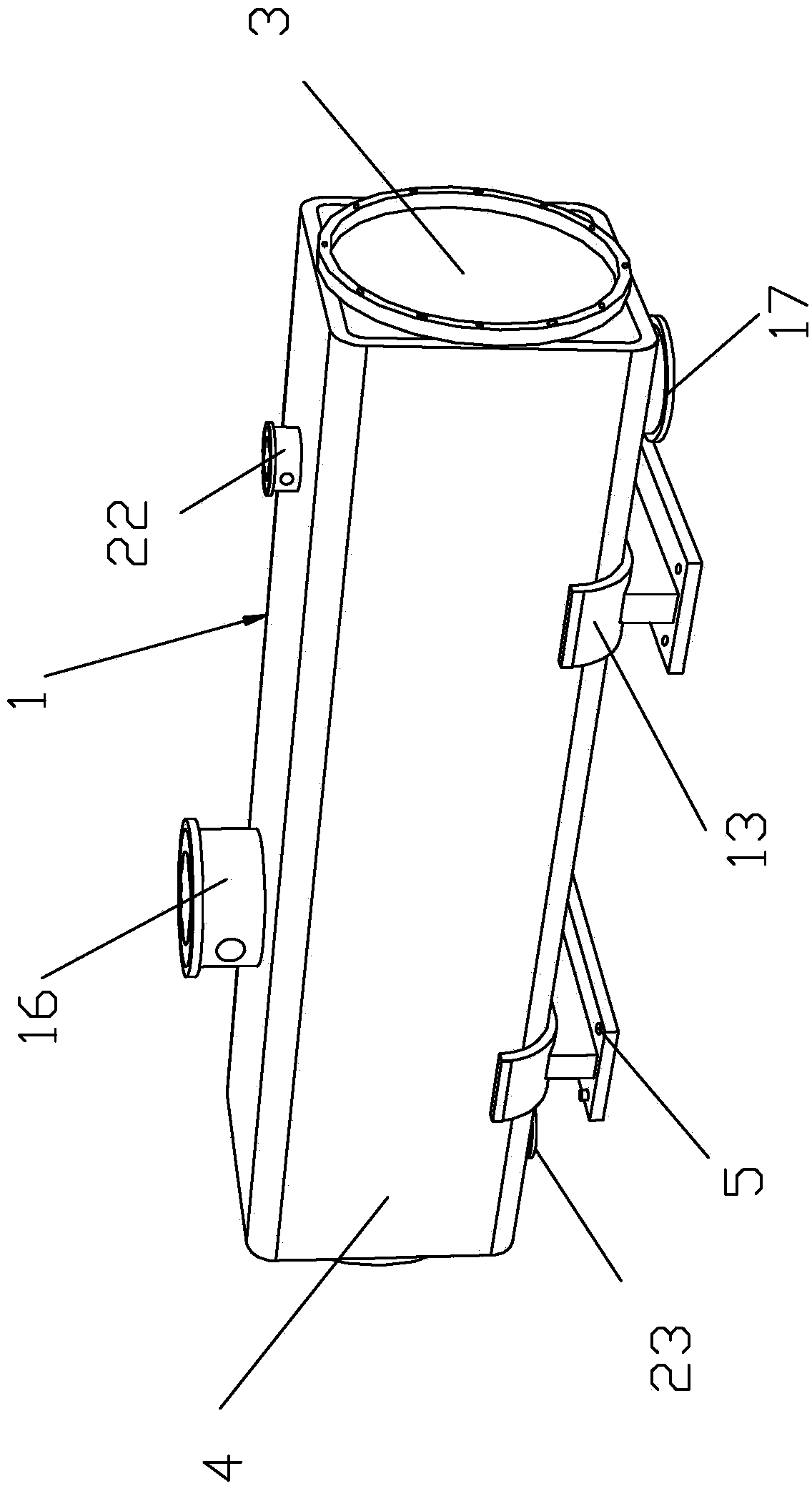
[0047] Such as Figure 1 to Figure 5 As shown, a shell and tube heat exchanger for producing anhydrous hydrofluoric acid includes a shell 1 and a head 2, the shell 1 includes an inner shell 3 and an outer shell 4, the inner shell 3 is a cylindrical hollow structure, and the inner shell 3 and the outer shell 4 are an integrated structure, a cavity 7 is provided between the inner shell 3 and the outer shell 4, the outer sides of the inner shell 3 are respectively fixedly connected with the head 2 to form a tube box, and the inner shell 3 is provided with a tube plate body 8, the tube plate body 8 includes a cylinder body 10, a tube bundle 11 and a baffle 12, the right side of the cylinder body 10 is fixedly connected with the inner shell 3, the tube plates 9 are respectively arranged on both sides of the tube bundle 11, and the tube bundle 11 passes through The cylinder body 10 extends into the tube box, the tube bundle 11 is a corrugated tube, and the baffle plate 12 is arrange...


PUM


Abstract

The invention discloses a tube-type heat exchanger for producing anhydrous hydrofluoric acid. The tube-type heat exchanger comprises a shell and a packing head, the outer sides of the two ends of an inner shell are fixedly connected with the packing head separately to form a tube box, a tube plate body is arranged inside the inner shell and comprises a cylinder, a tube bundle and a deflection baffle, the right side of the cylinder is fixedly connected with the inner shell, the two ends of the tube bundle are connected to the side face of the cylinder separately, and the tube bundle penetratesthrough the cylinder and extends into the tube box. A manufacturing method comprises the following steps of 1, manufacturing and assembly of the shell; 2, manufacturing and assembly of the tube platebody; 3, splicing of the tube plate body and the shell; 4, splicing of the shell and the packing head. The tube-type heat exchanger is simple in structure, low in cost and wide in flow cross section,limescale is easy to clean away, and the heat exchanger can be used under the high-temperature, high-pressure and strong-acid conditions, and simultaneously applied to three fluids; the fluid at the outermost layer is used for weakening the temperature influence of the fluid on the shell, the thermal stress is eliminated to the greatest extent, and the service life of the heat exchanger is prolonged.

Description

technical field [0001] The invention relates to the technical field of heat exchangers, in particular to a tube-and-tube heat exchanger for producing anhydrous hydrofluoric acid and a manufacturing method. Background technique [0002] A heat exchanger is a device that transfers part of the heat of a hot fluid to a cold fluid. Heat exchangers play an important role in chemical industry, petroleum, power, food and many other industrial productions. In the field of chemical production, heat exchangers can be used as heaters, coolers, condensers, evaporators and reboilers, etc., and are widely used. . [0003] The tube-and-tube heat exchanger is the most widely used heat exchanger in chemical and alcohol production. The structure of the tube-and-tube heat exchanger is simple, compact, and cheap. Both ends of the shell, the connection between the tube bundle and the tube sheet and the shell are rigid, and there are two fluids at different temperatures inside and outside the tu...

Claims


Application Information

Patent Timeline
IPC IPC(8): F28D7/16F28F1/08F28F9/00F28F9/12F28F9/22F28F9/24
CPCF28D7/16F28F1/08F28F9/00F28F9/12F28F9/22F28F9/24F28F2265/28F28F2275/06
Inventor 朱博超包国华兰贵杭
Owner 浙江森田新材料有限公司
Why Eureka
Try Eureka