
Slag discharge structure of secondary combustor

A technology of secondary combustion chamber and melting chamber, which is applied in the field of slagging structure of the secondary combustion chamber, which can solve the problems of inconvenient slagging and easy blockage of the secondary combustion chamber, and achieve the effects of complete combustion, accelerated flow and simplified structure

Active Publication Date: 2019-01-22
XINZHONGTIAN ENVIRONMENTAL PROTECTION
View PDF5 Cites 6 Cited by
  • Summary
  • Abstract
  • Description
  • Claims
  • Application Information

AI Technical Summary

Problems solved by technology

[0004] The object of the present invention is to provide a slagging structure for the second combustion chamber to solve the problem of inconvenient slagging and easy blockage of the second combustion chamber

Method used


Image

  • Slag discharge structure of secondary combustor
  • Slag discharge structure of secondary combustor
  • Slag discharge structure of secondary combustor

Examples


Embodiment Construction

[0021] The following is a further detailed description through specific implementations:

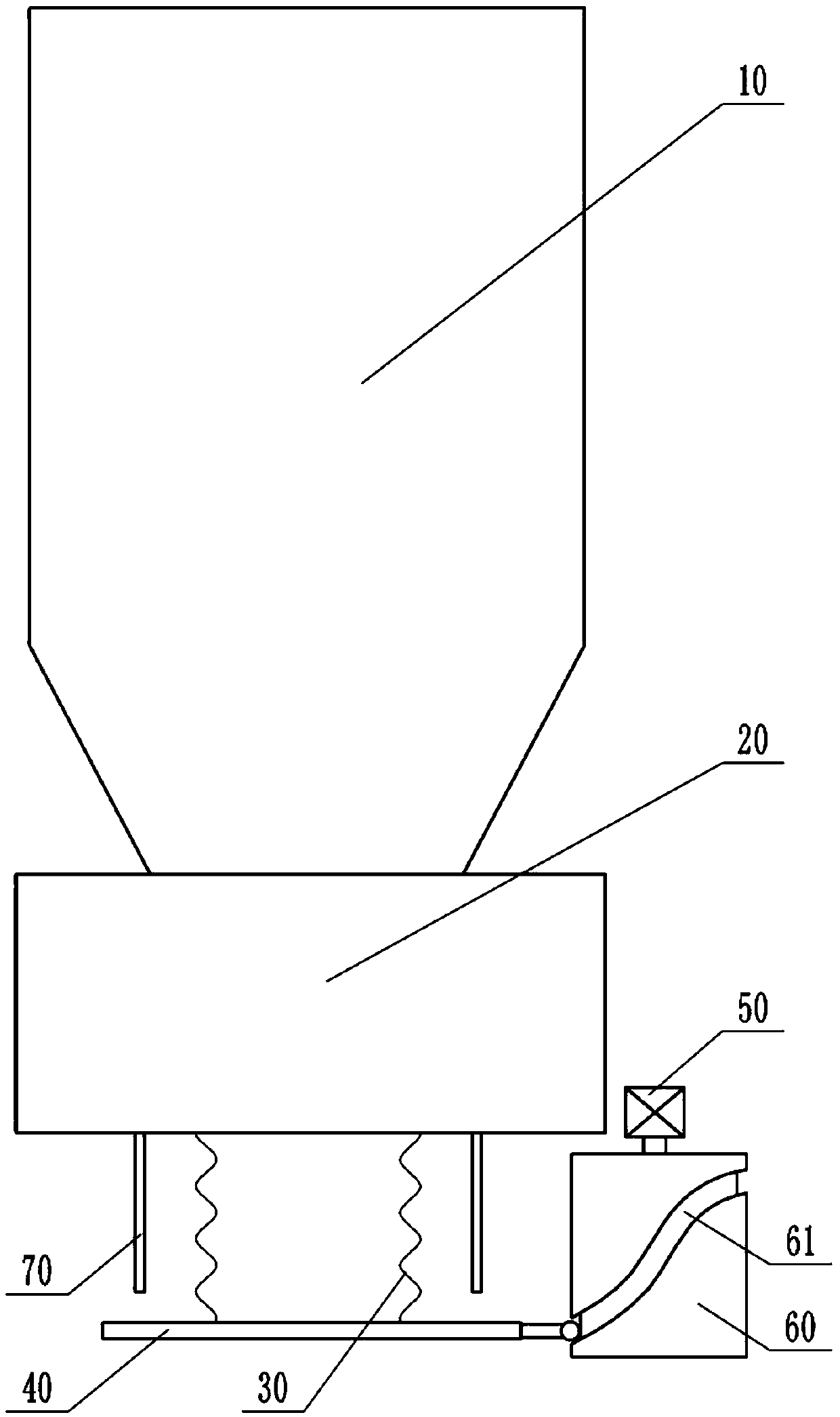
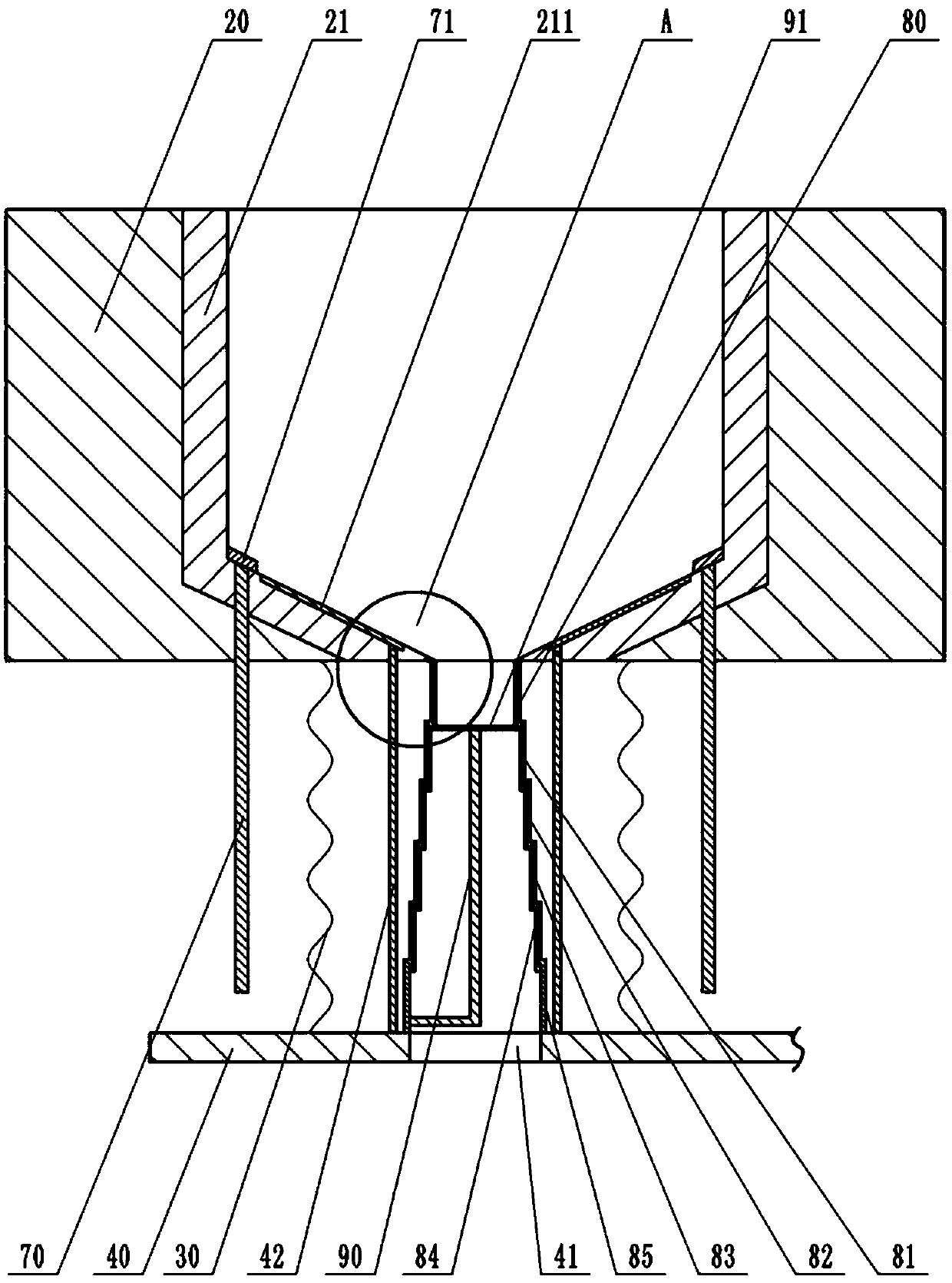
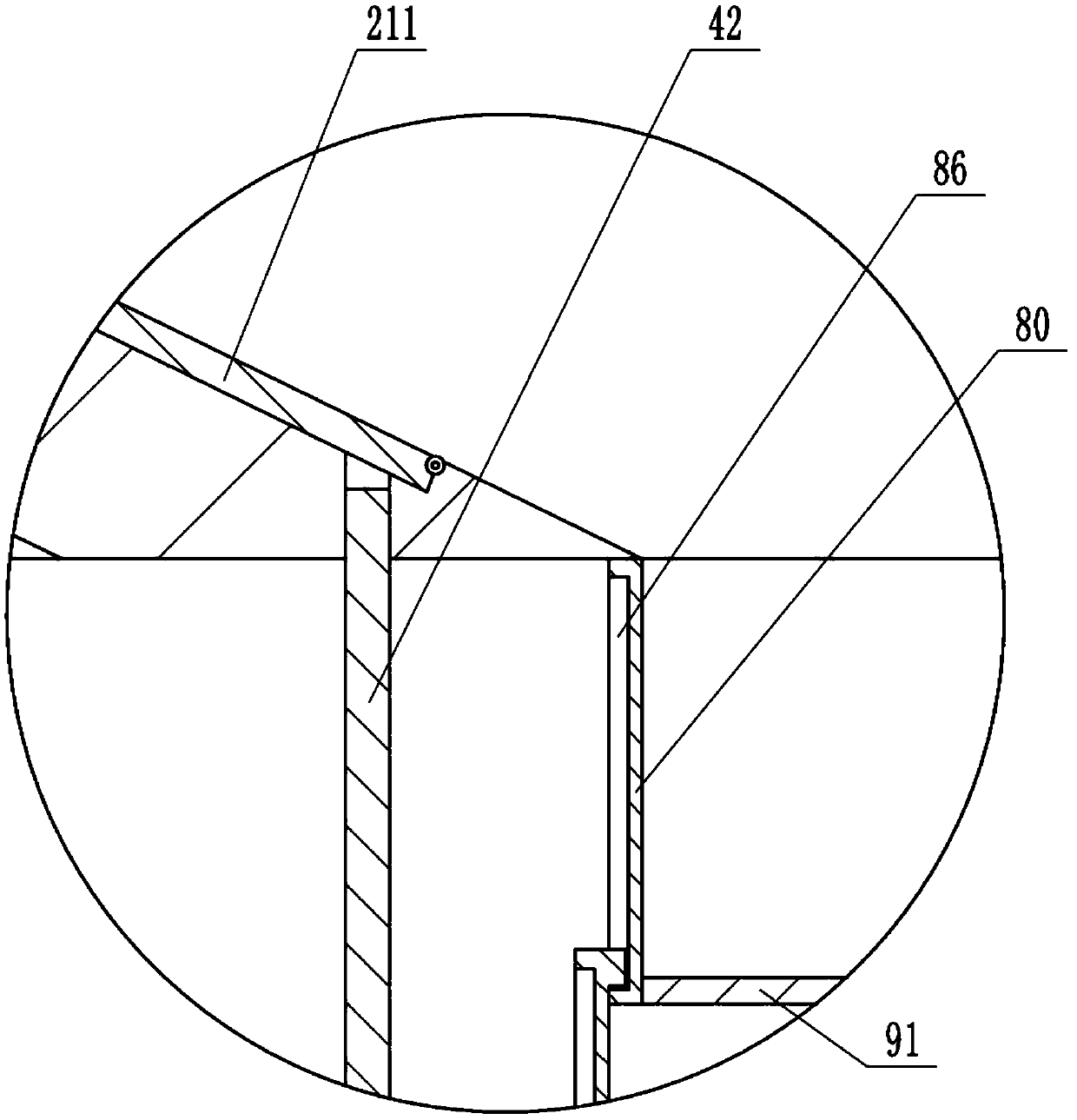
[0022] The reference signs in the drawings of the specification include: second combustion chamber 10, melting unit 20, melting chamber 21, turning plate 211, return spring 212, bellows 30, bottom plate 40, through hole 41, top rod 42, motor 50, rotation Column 60, curved groove 61, extension rod 62, push rod 70, annular scraper 71, fixed tube 80, first annular tube 81, second annular tube 82, third annular tube 83, fourth annular tube 84, The fifth annular cylinder 85, the limiting groove 86, the connecting rod 90, and the push plate 91.

[0023] The embodiment is basically as attached figure 1 As shown: the slag discharge structure of the second combustion chamber includes a melting unit 20 which is arranged at the lower end of the second combustion chamber 10. The melting unit 20 includes a heat preservation base and a melting chamber 21 located in the heat preservation base, and a combus...


PUM


Abstract

The invention belongs to the technical field of incinerator supporting equipment and particularly discloses a slag discharge structure of a secondary combustor. The slag discharge structure comprisesa melting unit arranged at the lower end of the secondary combustor; the melting unit includes an insulation base and a melting chamber arranged in the insulation base; a combustion mechanism to meltslag is arranged in the melting chamber; a slag discharge mechanism is connected to the lower end of the melting chamber. The the slag discharge structure herein helps effectively remove the slag generated during operating of the secondary combustor; slag discharging is convenient and reliable; the existing application needs can be effectively met.

Description

Technical field [0001] The invention belongs to the technical field of incinerator supporting equipment, and particularly relates to a slag discharge structure of a second combustion chamber. Background technique [0002] Rotary kiln incinerator refers to an incinerator in which a refractory lining furnace is installed inside a cylindrical body made of steel. The rotary kiln incinerator is installed slightly inclined compared to the horizontal position. While the rotary kiln rotates slowly, the waste supplied from the upper part is transferred to the lower part, and air is supplied from the front or the rear to burn it. Usually, a secondary combustion chamber is installed after the rotary kiln, so that the toxic and harmful gases that have not been completely burned by the pyrolysis in the previous stage can be completely burned in the oxidation state at a higher temperature. [0003] At present, the treatment of industrial hazardous waste generally uses rotary kiln with second co...

Claims


Application Information

Patent Timeline
IPC IPC(8): F23G5/14F23G5/44
Inventor 朱庆毅黄爱军胡茂丽毛小英郑伟阳杨
Owner XINZHONGTIAN ENVIRONMENTAL PROTECTION
Learn More