
A kind of bog recovery processing system and processing technology

A technology of recycling and processing technology, applied in the field of BOG recycling and processing system and processing technology, can solve the problems of environmental protection impact, economic damage, energy consumption and economic loss, avoid direct emissions, increase greenhouse effect, reduce production cost effect

Active Publication Date: 2019-06-11
陕西嘉恒凯达信息科技有限公司
View PDF7 Cites 0 Cited by
  • Summary
  • Abstract
  • Description
  • Claims
  • Application Information

AI Technical Summary

Problems solved by technology

However, liquefied natural gas is stored and transported at around -160°C, which is easily affected by external heat intrusion and other factors, resulting in a large amount of BOG (boil-off gas), causing overpressure of LNG station equipment and affecting the safe operation of the station. Among the greenhouse gases, CH 4 (methane) is second only to CO 2 The direct emission of BOG will not only cause energy consumption and economic loss, but also affect environmental protection
[0003] At present, most of the large-scale LNG receiving stations adopt a combination of direct compression and recondensation process to solve the problem of BOG generation. This process uses the cold energy of LNG itself, and the energy consumption is greatly reduced. However, when the LNG station has no output or BOG is generated When the amount is too large, the BOG has to be treated by direct compression or direct combustion through the torch, which will cause increased energy consumption, economic damage and environmental pollution.

Method used


Image

  • A kind of bog recovery processing system and processing technology

Examples


Embodiment Construction

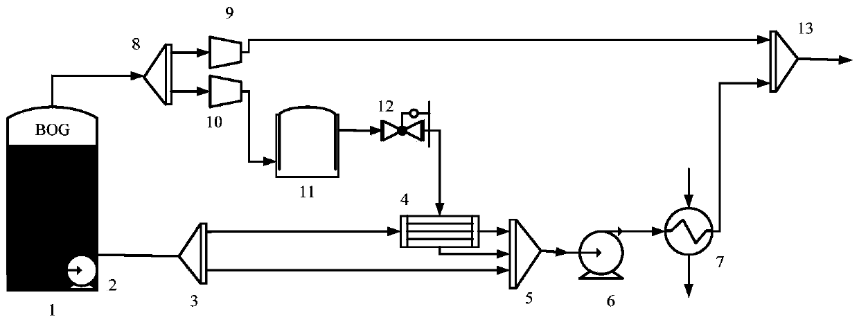
[0020] Attached below figure 1 The specific embodiments of the present invention will be described in detail, but it should be understood that the protection scope of the present invention is not limited by the specific embodiments. Based on the embodiments of the present invention, all other embodiments obtained by those of ordinary skill in the art without creative work shall fall within the protection scope of the present invention.

[0021] A BOG recovery treatment system and treatment process provided by the present invention include: LNG storage tank 1, in-tank pump 2, first distributor 3, recondenser 4, first mixer 5, high pressure pump 6, vaporizer 7. The second distributor 8, the first compressor 9, the second compressor 10, the compressed BOG storage tank 11, the pressure reducing valve 12, and the second mixer 13;

[0022] The in-tank pump 2 is arranged at the bottom of the LNG storage tank 1, the inlet end of the first distributor 3 is in communication with the in-tank...


PUM


Abstract

The invention discloses a BOG recovering and treating system and a treating technology, and belongs to the technical field of BOG recovering and treating. A tank internal pump of the treating system is arranged on the bottom of an LNG storage tank, a first respective transportation device is communicated with an after-condenser and a first mixed transportation device, an outlet of the first mixedtransportation device is communicated with an inlet of a high pressure pump, an outlet of the high pressure pump is communicated with an inlet of a vaporizer, an outlet of the vaporizer is communicated with a first inlet of a second mixed transportation device, an inlet of a second respective transportation device is formed in the top of the LNG storage tank, two outlets formed in the second respective transportation device are communicated with inlets of a first compressor and a second compressor respectively, an outlet of the first compressor is communicated with an inlet of the second mixedtransportation device, an outlet of the second compressor is communicated with an inlet of a compressed BOG storage tank, and an outlet of the compressed BOG storage tank is communicated with the after-condenser through a reducing valve. By means of the treating system, the production cost is reduced, and the situation that BOG discharging increases a greenhouse effect is prevented, so that the treating system plays a part in protecting the environment.

Description

Technical field [0001] The invention relates to the technical field of BOG recovery treatment, in particular to a BOG recovery treatment system and treatment process. Background technique [0002] With the development of social economy, energy shortage and environmental pollution problems have become increasingly prominent, the use of clean energy has become one of the themes of energy consumption in the world today. Natural gas has high calorific value, low pollution, small volume after liquefaction, and convenient storage for transportation. , And is widely used. However, liquefied natural gas is stored and transported at around -160°C, which is extremely vulnerable to the intrusion of external heat and other factors, resulting in a large amount of BOG (boiling gas), causing overpressure in the LNG station equipment, affecting the safe operation of the station, and producing Among the greenhouse gases, CH 4 (Methane) is second only to CO 2 The direct emission of BOG will not o...

Claims


Application Information

Patent Timeline
Patent Type & Authority Patents(China)
IPC IPC(8): F17C7/04F17C13/00F17D3/01
CPCF17C7/04F17C13/00F17D3/01
Inventor 肖荣鸽戴政靳文博高旭马钢
Owner 陕西嘉恒凯达信息科技有限公司
Learn More