Combustion chamber for natural gas engine
A combustion chamber and engine technology, applied in the direction of engine components, machines/engines, mechanical equipment, etc., can solve problems such as energy consumption, and achieve the effect of improving utilization
Inactive Publication Date: 2019-01-22
TIANJIN UNIV
View PDF4 Cites 0 Cited by
- Summary
- Abstract
- Description
- Claims
- Application Information
AI Technical Summary
Problems solved by technology
Some solutions to design combustion chambers with the help of nozzles, most of them are pre-combustion in the pre-mixed combustion chamber, and then sprayed into the main combustion chamber with the help of high-pressure pumps to optimize the combustion conditions, so that the pressure provided by the outside also consumes additional energy
Method used
View moreImage
Smart ImageViewing Examples

Examples
Embodiment Construction
Login to View More PUM
 Abstract
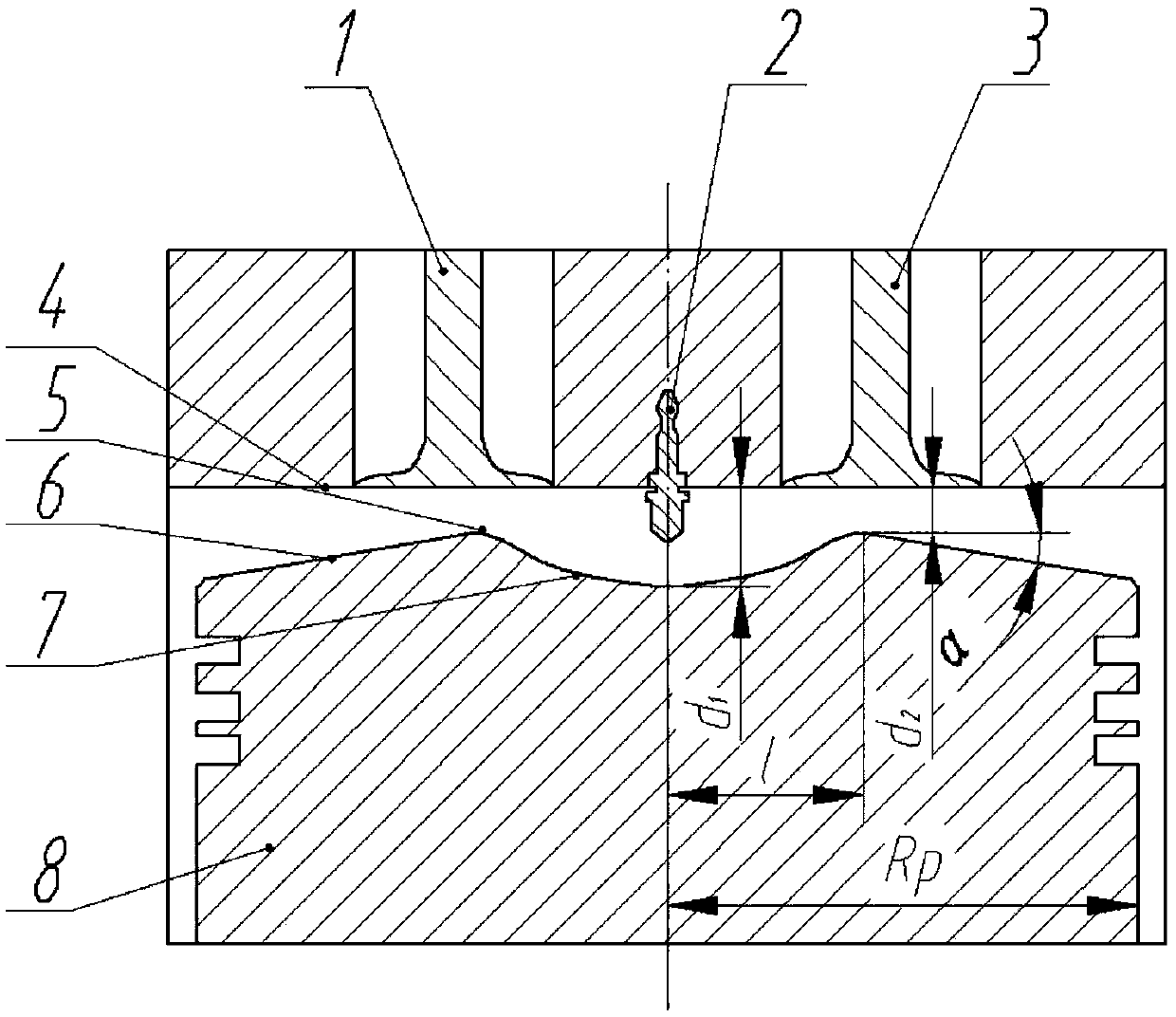
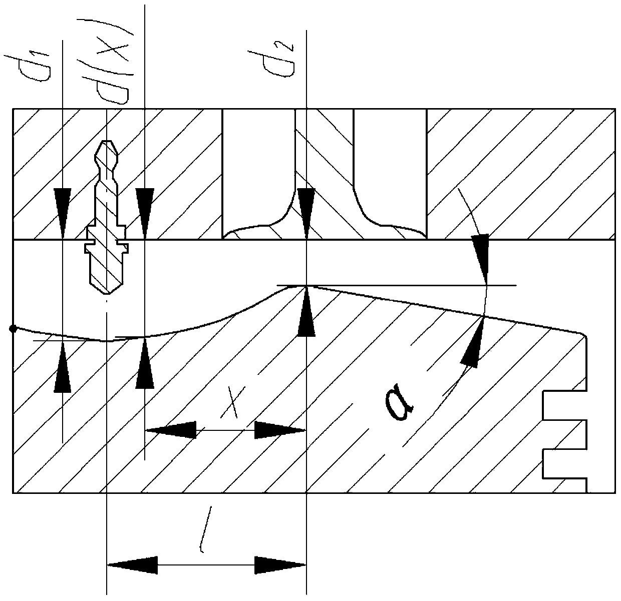
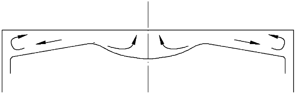
The invention relates to a combustion chamber for a natural gas engine. The combustion chamber is a closed area composed of a cylinder sleeve, a piston and a cylinder cover, a spark plug is arranged at the position, in the middle of the combustion chamber, of the cylinder cover, and the bottom of the cylinder cover is flat. The combustion chamber is characterized in that the top of the piston hasan uneven shape and comprises a gradual contraction part, a throat part and an expansion pare from inside to outside with the center line of the piston as a symmetry axis; the gradual contraction partexpands outwards in the radial direction of the piston from the center line of the piston, the cross section area gradually decreases, and the gradual contraction ends at the throat part; the cross section area of the throat part is the smallest; the expansion part extends outwards in the radial direction of the piston, and the cross section area gradually increases; the cross section curve of the gradual contraction part is designed according to the Witoszynski formula.
Description
technical field The invention relates to a combustion chamber structure for a natural gas engine, which relates to the technical field of engines, in particular to the design of the engine combustion chamber. Background technique In recent years, with the increasing consumption of oil and the increasingly serious environmental problems, many countries are looking for alternative resources of oil. Due to the good thermodynamic properties of natural gas, more and more people pay attention to natural gas. At present, most natural gas engines are simply refitted from existing gasoline engines and diesel engines, which cannot fully adapt to natural gas fuel, and the squeeze flow of natural gas in the cylinder is not strong and the flow velocity is low, resulting in some abnormal Combustion shortens the life of the engine. In order to further optimize the natural gas engine, it is necessary to make a targeted design, especially a design that can rationally organize the combustio...
Claims
Login to View More Application Information
Patent Timeline
 Patent Type & Authority Applications(China)
IPC IPC(8): F02F3/26F02F3/24F02F3/28
CPCF02F3/24F02F3/26F02F3/28
Inventor 潘家营王磊卫海桥舒歌群刘昌文陈林
Owner TIANJIN UNIV
Features
- R&D
- Intellectual Property
- Life Sciences
- Materials
- Tech Scout
- Unparalleled Data Quality
- Higher Quality Content
- 60% Fewer Hallucinations
Learn More Browse by: Latest US Patents, China's latest patents, Technical Efficacy Thesaurus, Application Domain, Technology Topic, Popular Technical Reports.
© 2025 PatSnap. All rights reserved.Legal|Privacy policy|Modern Slavery Act Transparency Statement|Sitemap|About US| Contact US: help@patsnap.com