A lifting platform for logistics

A lifting platform and logistics technology, applied in the direction of lifting frame, lifting device, etc., can solve problems such as hidden safety hazards and the whereabouts of lifting trolleys, etc., and achieve the effects of efficient cargo loading, convenient loading, and simple structure.

Active Publication Date: 2020-06-09
陈章银
View PDF8 Cites 0 Cited by
  • Summary
  • Abstract
  • Description
  • Claims
  • Application Information

AI Technical Summary

Problems solved by technology

[0002] In the existing logistics system, lifting trolleys are often used to pick and place items located above. The existing lifting trolleys are generally driven by hydraulic cylinders, but if the hydraulic oil unloads the trolley after the hydraulic cylinder pushes it up, the lifting The trolley will fall, which will pose a safety hazard

Method used


Image

  • A lifting platform for logistics
  • A lifting platform for logistics
  • A lifting platform for logistics

Examples


no. 1 approach

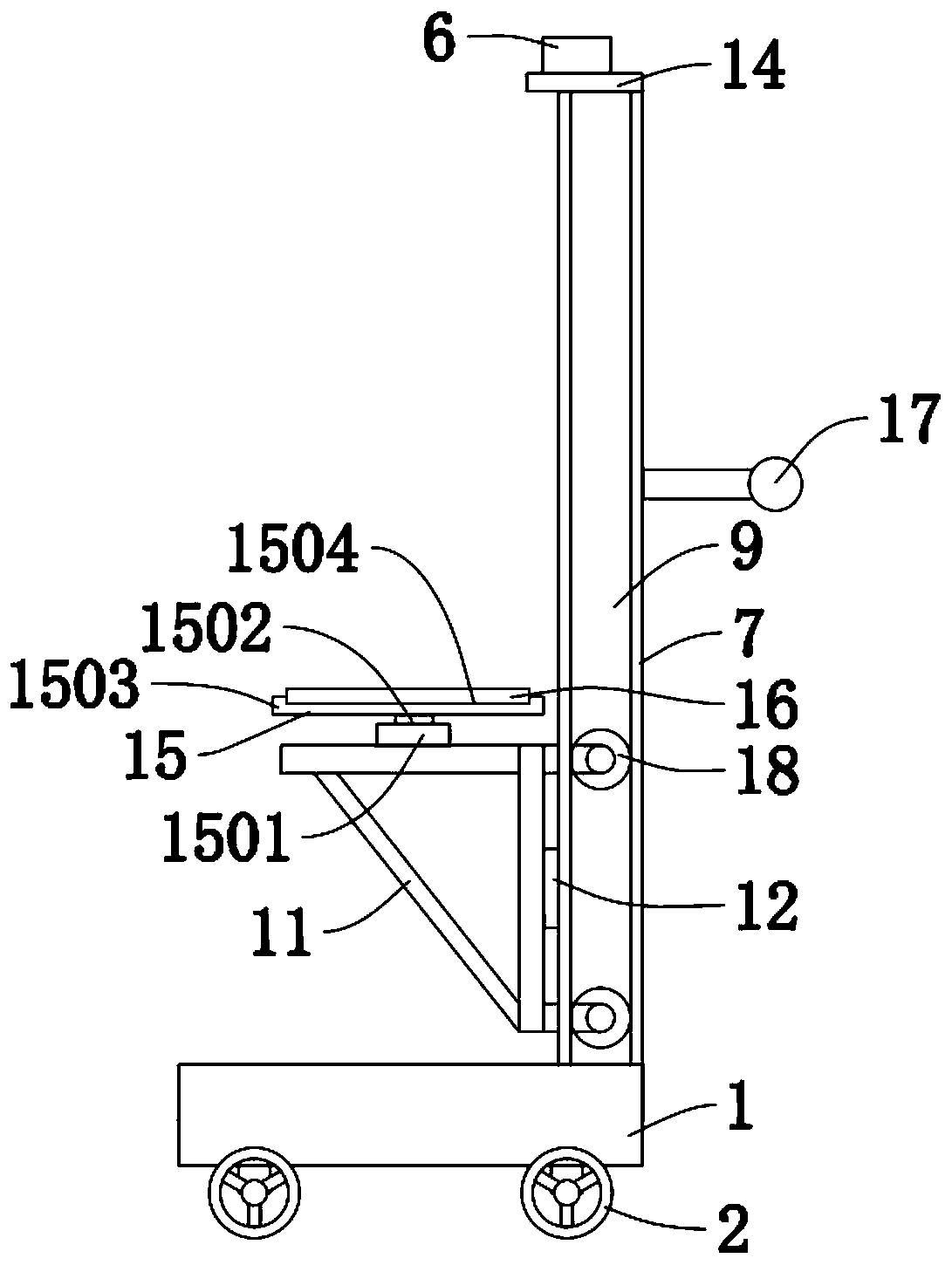
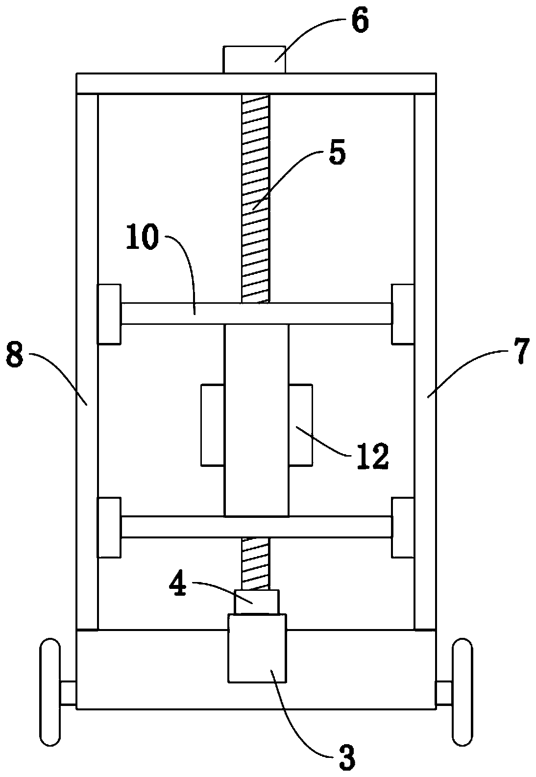
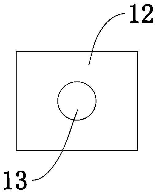
[0018] First implementation: see Figure 1-3 , a lifting platform for logistics, including a base 1, wheels 2 are installed on both sides of the base 1, and a first support rod 7 and a second support rod 8 are fixedly welded on the upper side of the base 1, so The inner sides of the first support bar 7 and the second support bar 8 are all provided with a slideway 9, and a pulley 18 is slidably connected on the slideway 9, and the pulley 18 can be on the inside of the first support bar 7 and the second support bar 8. Moving up and down in the slideway 9, the slideway 9 plays a position-limiting role, the pulley 18 is fixedly connected with a support beam 10, and one side of the support beam 10 is fixedly welded with a support frame 11, and the set support beam 10 and The support frame 11 can play the role of supporting goods, the right side of the middle part of the support frame 11 is fixedly connected with a slider 12, the slider 12 has a bolt hole 13, and a motor is embedded...

no. 2 approach

[0025] The second embodiment: a lifting platform for logistics, including a base 1, wheels 2 are installed on both sides of the base 1, and a first support rod 7 and a second support rod are hinged on the upper side of the base 1 8. A slideway 9 is provided inside the first support rod 7 and the second support rod 8, and a pulley 18 is slidably connected to the slideway 9, and a support beam 10 is fixedly connected to the pulley 18. One side of the support beam 10 is fixedly welded with a support frame 11, and the middle right side of the support frame 11 is fixedly connected with a slider 12, and the slider 12 is provided with a bolt hole 13, and the bottom side of the base 1 is embedded with a There is a motor 3, the upper output end of the motor 3 is connected with a screw mandrel 5 through a coupling 4, the screw mandrel 5 runs through the slider 12, and the screw mandrel 5 is threadedly connected with the bolt hole 13 on the slider 12, The upper end of the screw mandrel 5...


PUM


Abstract

The invention discloses a lifting platform for logistics. The lifting platform comprises a base and is characterized in that wheels are mounted on two sides of the base, a first support rod and a second support rod are fixedly welded to one side of the upper portion of the base, slideways are arranged on the inner sides of the first support rod and the second support rod, slide wheels are slidablyconnected to the slideways, support beams are fixedly connected to the slide wheels, a support rack is fixedly welded to one sides of the support beams, a slider is fixedly connected to the right side of the middle of the support rack and provided with a bolt hole, a motor is embedded into one side of the lower portion of the base, a screw rod is connected to the upper-end output end of the motorthrough a coupler, the screw rod penetrates the slider and connected with the bolt hole in the slider in a threaded manner, and the upper end of the screw rod is fixed on one sides of the upper endsof the first support rod and the second support rod. The lifting platform is reasonable in design, simple in structure, good in stability, low in manufacturing cost, capable of facilitating shelving and worthy of energetic popularization.

Description

technical field [0001] The invention relates to the technical field of logistics lifting platforms, in particular to a lifting platform for logistics. Background technique [0002] In the existing logistics system, lifting trolleys are often used to pick and place items located above. The existing lifting trolleys are generally driven by hydraulic cylinders, but if the hydraulic oil unloads the trolley after the hydraulic cylinder pushes it up, the lifting The trolley will fall, thereby bringing potential safety hazards. Therefore, it is necessary to invent a lifting platform for logistics to solve the above problems. Contents of the invention [0003] The object of the present invention is to provide a lifting platform for logistics, so as to solve the problems raised in the above-mentioned background technology. [0004] In order to achieve the above object, the present invention provides the following technical solutions: a lifting platform for logistics, including a ...

Claims


Application Information

Patent Timeline
Patent Type & Authority Patents(China)
IPC IPC(8): B66F7/06B66F7/28
CPCB66F7/0608B66F7/0625B66F7/28
Inventor 陈章银
Owner 陈章银
Why Eureka
Try Eureka