Walking assist device
A technology of walking assistance and energy storage mechanism, which is applied in the direction of devices to help people walk, physical therapy, etc., can solve the problems of complex systems, poor wearing comfort, and high cost, and achieve good wearing comfort, low cost of wearing comfort, and structural simple effect
- Summary
- Abstract
- Description
- Claims
- Application Information
AI Technical Summary
Problems solved by technology
Method used
Image

Examples
Embodiment 1
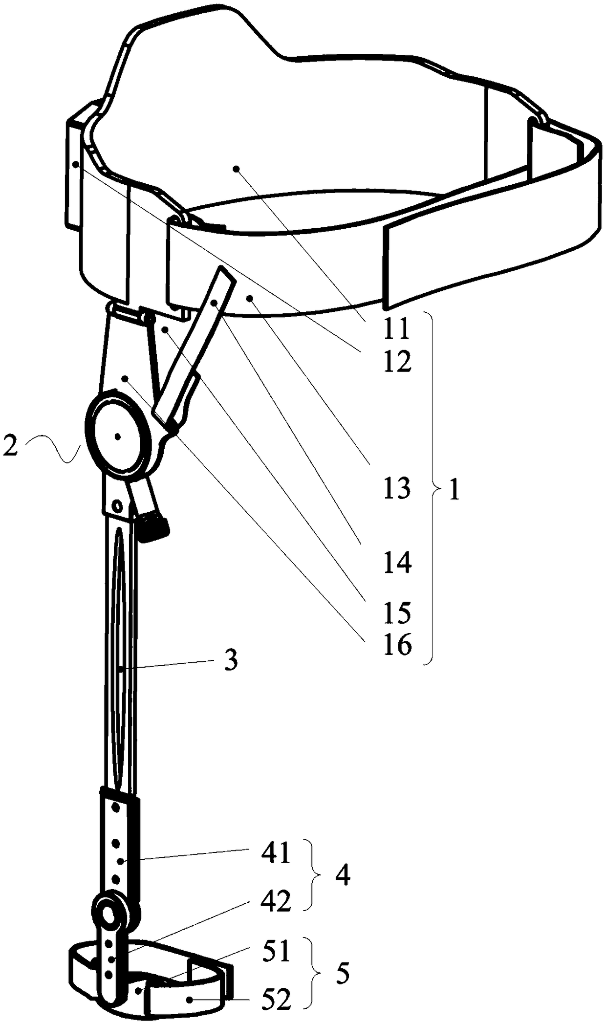
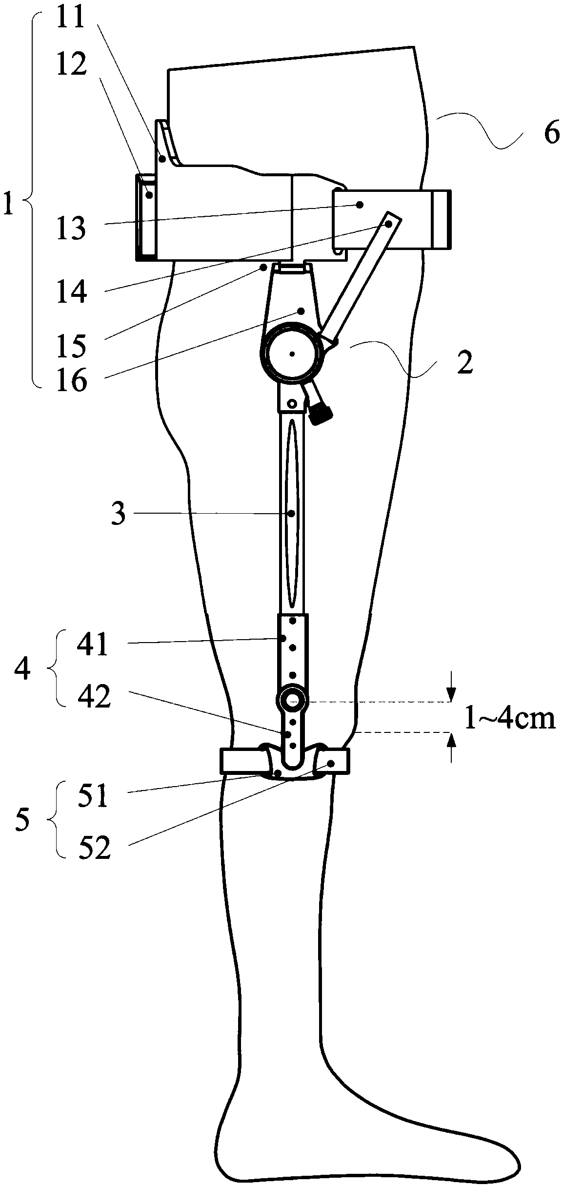
[0046] Such as figure 1 To the walking assist device shown in Figure 4, including the following:
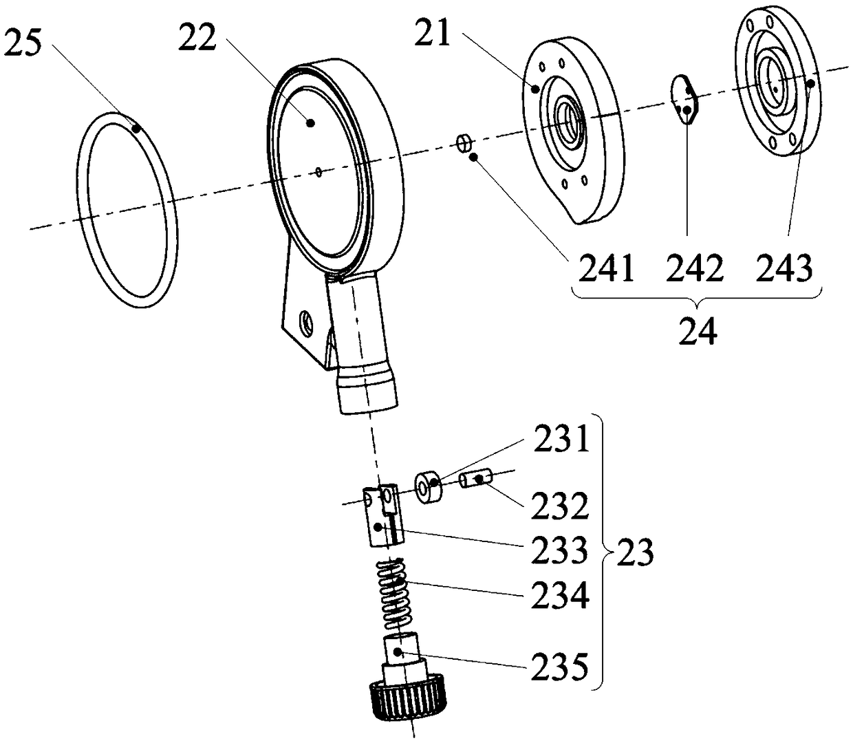
[0047](1) The device includes a waist wearing assembly 1 , a hip joint energy storage mechanism 2 , a swing connector 3 , a knee joint rotating assembly 4 and a calf wearing assembly 5 . Wherein, the waist wearing assembly 1 is used for binding the hip joint energy storage mechanism 2 on the waist of the user 6, see figure 1 with 2 , comprising a waist retainer 11, a controller 12, a waist binding belt 13, an adjustment belt 14, a rotating shaft 15 and a hem bracket 16, the hip joint energy storage mechanism 2 is fixedly connected to the waist wearing assembly 1, including a cam 21, a swinging machine Frame 22, push rod mechanism 23, angle sensor 24 and luminous ring 25, push rod mechanism 23 includes roller 231, roller shaft 232, spring guide rod 233, spring 234 and spring preload knob 235, angle sensor 24 includes magnet 241, electric The magnetic sensor 242 and the sensor f...
Embodiment 2
[0056] Such as Figure 5 , shown in Fig. 6 (a), Fig. 6 (b), differs from Embodiment 1 in that the cam 21 is an inner cam, and the cam 21 is provided with a cam groove 211 matching the inner contour line, and the roller 231 is installed on the side of spring guide rod 233, and is arranged in the described cam groove, and described roller 231 is kept in contact with the inner contour line of cam 21 by force sealing mode under spring 234 spring force and does not disengage. As shown by the dotted line in Fig. 6(a), when the lower limb on the wearing side is on the heel ground at the end of the swing phase, the flexion angle of the lower limb is 30° at this time, and the walking assist device starts to absorb the consumption of the lower limb from the swing phase to the support phase. Dispersed mechanical energy, the swing plate frame 22 and the push rod mechanism 23 installed on it are driven by the swing connector 3 to rotate around the center of rotation of the cam 21. At this ...
Embodiment 3
[0058] Such as Figure 7 , shown in Fig. 8 (a), Fig. 8 (b), differ from Embodiment 1 in that the cam 21 is formed by an eccentric installation of a circular wheel body. In this example, the center of rotation of the roller 231 is installed on the spring On the central axis of the guide rod 233, as shown by the dotted line in Fig. 8(a), when the lower limb on the wearing side is in the heel-ground at the end of the swing phase, the flexion angle of the lower limb is 30° at this time, and the walking assist device begins to absorb the movement of the lower limb. The oscillating phase transfers to the dissipated mechanical energy of the supporting phase, the oscillating plate frame 22 and the push rod mechanism 23 installed on it rotate around the center of rotation of the cam 21 under the drive of the oscillating connector 3, and the roller 231 moves from the cam 21 to the actual The starting point of the profile begins to rotate along the cam push section, the center distance b...
PUM
 Abstract
Description
Claims
Application Information
 - R&D
- Intellectual Property
- Life Sciences
- Materials
- Tech Scout
- Unparalleled Data Quality
- Higher Quality Content
- 60% Fewer Hallucinations
Browse by: Latest US Patents, China's latest patents, Technical Efficacy Thesaurus, Application Domain, Technology Topic, Popular Technical Reports.
© 2025 PatSnap. All rights reserved.Legal|Privacy policy|Modern Slavery Act Transparency Statement|Sitemap|About US| Contact US: help@patsnap.com