An electronic communication equipment mounting box

A technology for electronic communication equipment and installation boxes, applied in mechanical equipment, design features of springs/shock absorbers, casings/cabinets/drawer components, etc., can solve the problem of broken lines, shorten the service life of installation boxes, Problems such as equipment crash

Active Publication Date: 2019-01-18
王媛玲
View PDF7 Cites 2 Cited by
  • Summary
  • Abstract
  • Description
  • Claims
  • Application Information

AI Technical Summary

Problems solved by technology

[0002] Installation boxes for placing electronic communication equipment are often seen on the road, which are mainly used for placing electronic mechanisms for line connection and control at various intersections; current installation boxes are generally fixed and installed on the ground directly by cement. , if a vehicle driving on the road accidentally hits the installation box, the installation box may be damaged under a large impact force, and the electronic equipment located in the installation box will also be damaged or the circuit inside will be damaged. The installation box needs to be replaced after being hit, which shortens the service life of the installation box

Method used


Image

  • An electronic communication equipment mounting box
  • An electronic communication equipment mounting box
  • An electronic communication equipment mounting box

Examples


Embodiment Construction

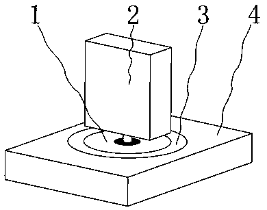
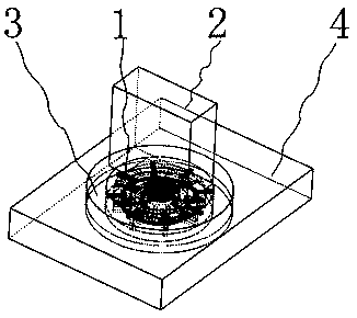
[0041] Such as figure 1 , 2 As shown, it includes support base 1, installation box 2, support rod 9, wherein as Figure 4 As shown, the foundation 4 is dug with a cylindrical pit 5 for placing the support base 1, such as image 3 As shown, the support base 1 is placed in the cylindrical pit 5, such as figure 2 As shown, the upper side of the outer edge of the support base 1 is fixed by concrete 3, and the lower end of the support rod 9 is installed on the support base 1, as Figure 5 As shown, the installation box 2 for installing electronic equipment is installed on the upper end of the support rod 9, and the installation box 2 is redundantly wound with multiple turns of signal transmission lines for buffering; as Figure 6 As shown, there is an annular chute 47 in the support base 1, and the triggering ring 16 is slidably installed in the annular chute 47. The outer ring surface of the triggering ring 16 and the inner groove surface of the annular chute 47 have a sliding...


PUM


Abstract

The invention belongs to the technical field of mounting boxes, in particular to an electronic communication equipment mounting box, which includes a support base, a mounting box, a support bar; underthe normal condition, that the support rod and the mounting box can keep the stable state without being impacted by the triggering mechanism, the limiting disk, the universal joint and the limiting mechanism, but the ordinary mounting box may be damaged when being impacted, and the signal transmission line in the mounting box is pulled out; When the mounting box is impacted, the mounting box andthe support rod will move horizontally in the impacted direction; As that support rod is disengage from the inner re of the universal joint under the action of the impact force, the mounting box is prevented from being damaged by the large impact force directly, the mounting box is protected, and the mounting box can be prevented from moving under the driving of the impact object, and the signal transmission line in the mounting box is pulled out; At that same time, the universal joint swing with the support rod so as to facilitate the support rod to smoothly disengage from the base.

Description

Technical field [0001] The invention belongs to the technical field of installation boxes, in particular to an installation box for electronic communication equipment. Background technique [0002] Installation boxes for placing electronic communication equipment are often seen on the road, which are mainly used for placing electronic mechanisms for line connection and control at various intersections; current installation boxes are generally fixed and installed on the ground directly by cement. , if a vehicle driving on the road accidentally hits the installation box, the installation box may be damaged under a large impact force, and the electronic equipment located in the installation box will also be damaged or the circuit inside will be damaged. The installation box after being hit needs to be replaced, which shortens the service life of the installation box. [0003] The present invention designs an electronic communication equipment installation box to solve the abov...

Claims


Application Information

Patent Timeline
IPC IPC(8): H05K5/02
CPCF16F7/00F16F2230/0023F16M13/00F16M2200/08
Inventor 罗鹏程陈晓红项炜涛
Owner 王媛玲
Why Eureka
Try Eureka