A delay switch circuit for resisting voltage fluctuation

A delay switch and switch circuit technology, applied in the electronic field, can solve the problems of short delay, narrow tunable range, increased programming and burning of chips, etc., and achieve the effect of rapid power-on

Pending Publication Date: 2019-01-18
BOWEI TECH
View PDF12 Cites 7 Cited by
  • Summary
  • Abstract
  • Description
  • Claims
  • Application Information

AI Technical Summary

Problems solved by technology

The existing solution has a short delay, a narrow tunable range, a slow rising edge when the power is turned on, or the need to delay the chip and then increase the problem of programming and burning

Method used


Image

  • A delay switch circuit for resisting voltage fluctuation
  • A delay switch circuit for resisting voltage fluctuation
  • A delay switch circuit for resisting voltage fluctuation

Examples


Embodiment 2

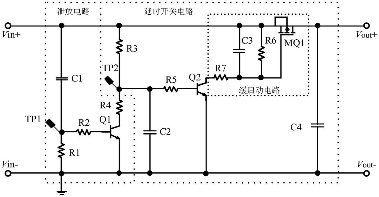
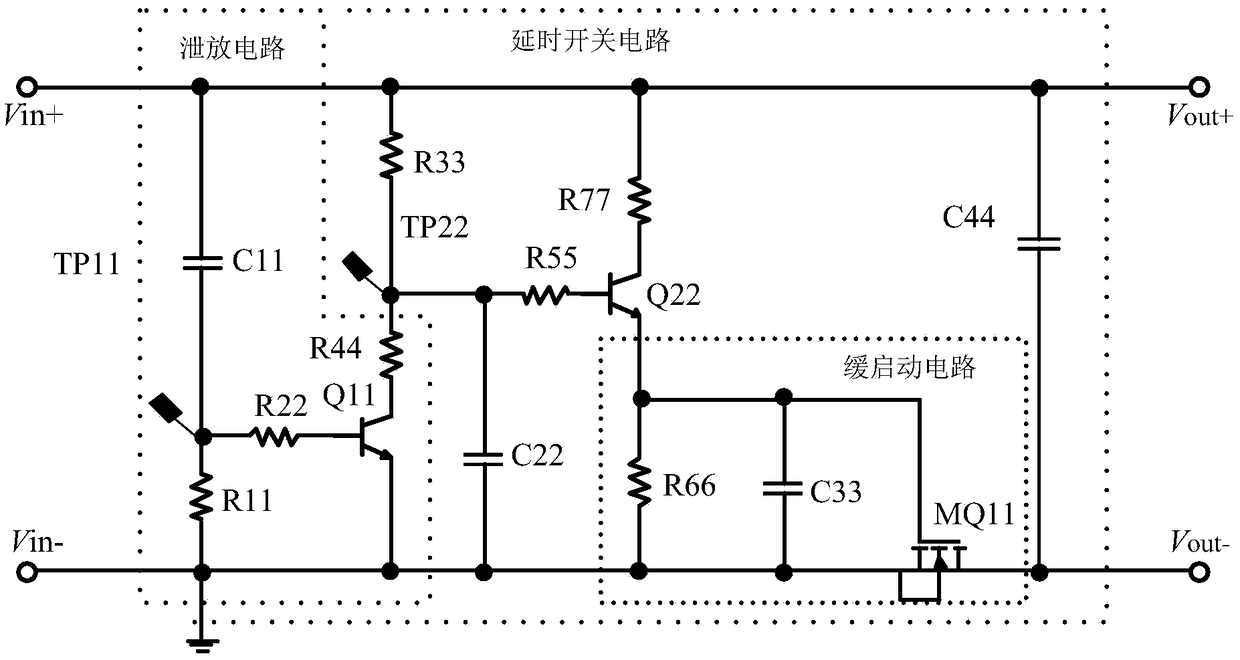
[0055] see figure 2 , on the basis of the first embodiment, the P-MOS tube is replaced with an N-MOS tube. The change of the tube type makes the slow-start drive circuit and the slow-start circuit slightly changed; the overall layout principle of the functional circuit is the same, and there is no difference here No longer.

[0056] Of course, this application does not rule out changing the NPN transistor to a PNP transistor based on the principle of permutation and combination to achieve a different circuit physical structure; but it does not exceed the above-mentioned circuit function principle.

[0057] One or more technical solutions provided in the embodiments of this application have at least the following technical effects or advantages:

[0058] The anti-voltage fluctuation delay switch circuit provided in the embodiment of the present application is based on the design of the slow start circuit, introduces the slow start drive circuit, and specifically sets the RC c...


PUM


Abstract

The invention belongs to the field of electronic technology, and discloses a delay switch circuit for resisting voltage fluctuation, the circuit comprising an input interface Vin +, an input interfaceVin- , an output interface Vout +, an output interface Vout- , a resistor R3, a capacitor C2, a resistor R5, a NPN transistor Q2, a capacitor C3, a resistor R6, a resistor R7, and a P-MOS transistorMQ1. The first end of R3 is connected to Vin +, and the second end of R3 is connected to Vin + via C2. The second end of R3 is connected to the base of Q2 via R5, and the emitter of Q2 is connected tothe Vin-. The first terminal of C3 is connected to Vin +, the second terminal of C3 is connected to the collector of Q2 through R7, R6 is connected to C3 in parallel, the gate of MQ1 is connected tothe second terminal of C3, the source of MQ1 is connected to Vin +, and the drain of MQ1 is connected to Vout +. The Vin- and the Vout- are grounded. The delay switch circuit with voltage fluctuationresistance provided by the invention can solve the technical problems of short delay time and narrow tunable range in the prior art.

Description

technical field [0001] The invention relates to the field of electronic technology, in particular to a time-delay switch circuit for resisting voltage fluctuations. Background technique [0002] With the widespread use of high-power equipment on the existing network, such as air conditioners and thermostats, the mains voltage will fluctuate to varying degrees at the moment of startup, which may cause other equipment in use to suddenly power off and then power on. It should be noted that in the circuit design, the chip has strict specifications for the power-on sequence of the power supply. If the sequence requirements are not met, for example, the mains voltage fluctuates, the residual voltage is not released in time after the device is powered off, and the power is turned on quickly, or If the power-on rising edge is discontinuous, etc., it will not be able to start normally, or some functions will be abnormal after starting. [0003] In this regard, the existing technolog...

Claims


Application Information

Patent Timeline
Patent Type & Authority Applications(China)
IPC IPC(8): H03K17/284H03K17/687
CPCH03K17/284H03K17/687H03K2217/0081
Inventor 李汝虎席德权蔡舒宏
Owner BOWEI TECH
Why Eureka
Try Eureka